Radio receiving method and radio receiving apparatus

Inactive Publication Date: 2001-05-15
PANASONIC CORP
View PDF13 Cites 30 Cited by
  • Summary
  • Abstract
  • Description
  • Claims
  • Application Information

AI Technical Summary

Problems solved by technology

However, since the BPF is large-sized, there is such a problem where if a BPF is equipped in a pager, the pager itself is unavoidably made large in size.
However, especially, since the resonance frequency of antenna Ant1 is identical to that of local oscillation signals, the local oscillation signals are radiated through antenna Ant1. This becomes unnecessary radiation waves and is received again.
If a phase difference exists between the unnecessary radiation waves and the receiving frequency (f0), noise is generated in the demodulation signals.
Furthermore, unnecessary radiation of intensive electric field strength is mixed from a circuit substrate member, at which local oscillator 7 cannot be shielded by a shield case 15, etc., into a mixer.
However, in the example of the abovementioned Patent Publication, although improvement of decreasing unnecessary radiation power from antenna was attempted, it is difficult to carry out an accurate orthogonal conversion by the mixer, and simultaneously the apparatus will be made large-sized, wherein the actual mounting area of electronic components is decreased, and the process work will be made cumbersome.
Furthe

Method used


Image

  • Radio receiving method and radio receiving apparatus
  • Radio receiving method and radio receiving apparatus
  • Radio receiving method and radio receiving apparatus

Examples


second embodiment

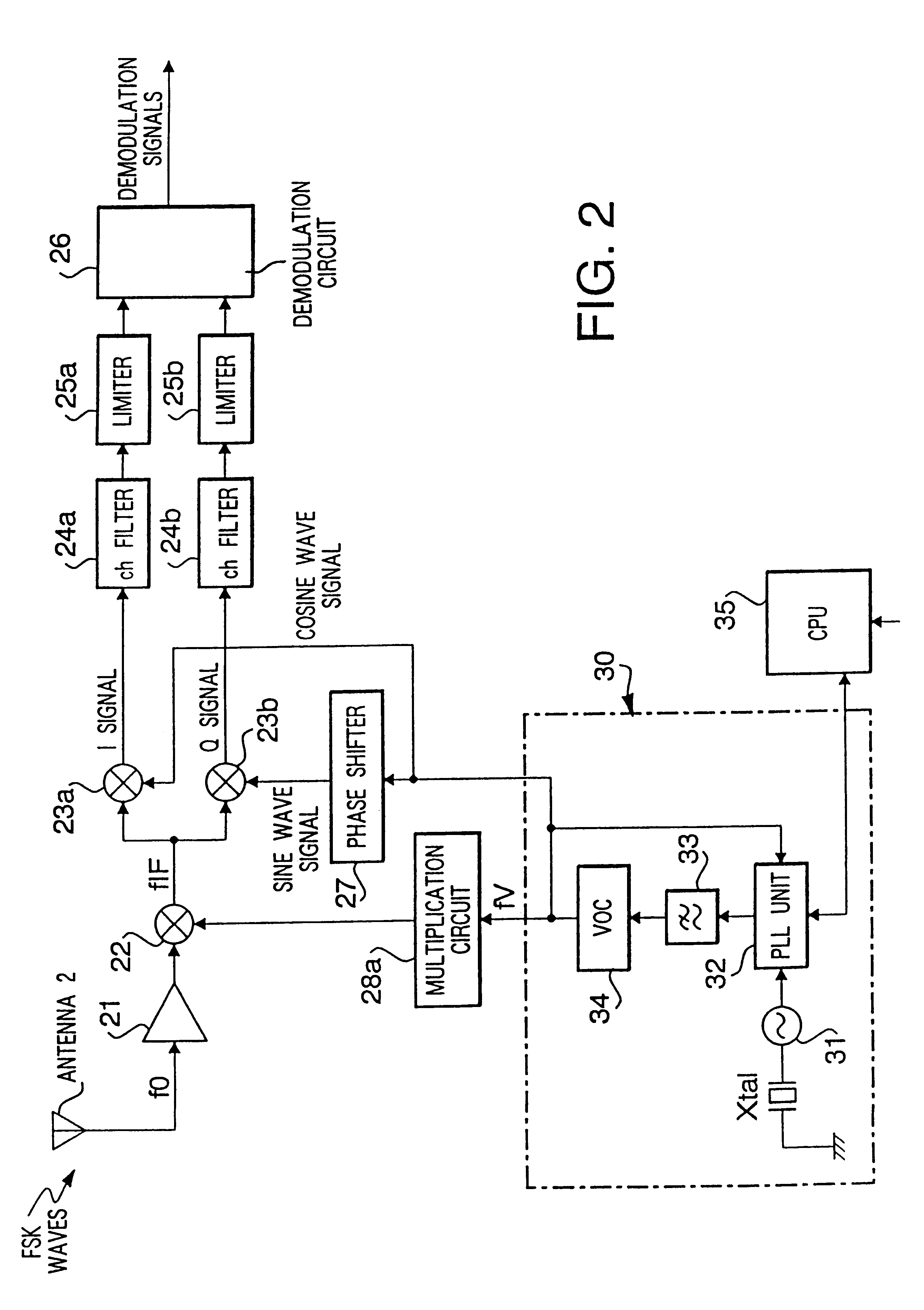
FIG. 2 is a block diagram showing a configuration of the second preferred embodiment. The basic construction of the second preferred embodiment is identical to that of the first embodiment shown in FIG. 1, wherein the second embodiment differs in that a multiplication circuit 29 is removed from a pass of supplying oscillation signals from the local oscillation unit 30 to mixer 23a and phase shifter 27.

The second preferred embodiment is provided with only a multiplication circuit 28a which multiplies "x" times the oscillation signals (fV) coming from the local oscillation unit 30 to sends the same to the mixer 22. Oscillation signals (fV) coming from the local oscillation unit 30 is directly supplied to the mixer 23b through the mixer 23a and phase shifter 27. All the other construction is identical to that of the first preferred embodiment.

Actions of the second preferred embodiment are the same as those of the first embodiment. However, the frequency relationship of frequency conver...

third embodiment

FIG. 3 is a block diagram showing a configuration of the third preferred embodiment.

The basic construction of the third embodiment is the same as that of the first embodiment shown in FIG. 1. However, the third embodiment differs in that a multiplication circuit 28 is removed from a pass of supplying oscillations from the local oscillation unit 30 to the mixer 22.

The third preferred embodiment is provided with only a multiplication circuit 29a which supplies oscillation signals (fV) coming from the local oscillation unit 30 to the mixer 23a after multiplying the same "y" times, shifts the phase of oscillation signals (fV) from the local oscillation unit 30 ninety degrees (90.degree.) by a phase shifter 27 and supplies the same to the mixer 23b. The oscillation signals (fV) coming from the local oscillation unit 30 are directly supplied to the mixer 22. All the other construction is identical to that of the first preferred embodiment.

Actions of the third preferred embodiment are the ...

fourth embodiment

FIG. 4 is a block diagram showing a configuration of the fourth preferred embodiment.

The fourth preferred embodiment has a feature of greatly varying the receiving frequencies (f0 to fn), which can meet a requirement where the service frequency bands are different according to districts.

The basic configuration is similar to that of the first preferred embodiment shown in FIG. 1. However, the fourth preferred embodiment is provided with an antenna varying circuit 20 for changing the tuning frequency of antenna Ant 2 by control signals to change the frequency received from CPU 35 and a variable high-frequency amplification circuit 21a for carrying out the high-frequency amplification by changing the tuning frequency by frequency changing control signals coming from CPU 35 to receiving signals (f0 to fn) coming from the antenna circuit 20.

Furthermore, variable multiplication circuits 28b, 29b which vary multiplication frequencies corresponding to the frequency changing control signals ...


PUM


Abstract

A radio receiving apparatus has a receiving section for receiving a radio signal, a local oscillating section for generating a first local oscillation signal and a second local oscillation signal, wherein the first local oscillation signal and the second local oscillation signal have each of a first frequency and a second frequency differing from a received frequency. The apparatus also has a frequency converting section for mixing the received signal output from the receiving section and the first local oscillation signal to output an intermediate frequency signal and an orthogonal converting section for orthogonal converting the intermediate frequency signal output with the second local oscillation signal.

Description

1. Field of the InventionThe present invention relates to a radio receiving method and a radio receiving apparatus which are used to obtain baseband signals by orthogonally converting radio receipt signals after being frequency-converted, when receiving and demodulating a simultaneous paging signal such as a pager, etc.2. Description of the Related ArtConventionally, a pager has been known as one of radio receiving apparatus which receive a simultaneous paging signal, telephone number and business of a transmission pager (caller) and display the same. A super heterodyne system has been employed for conventional pagers. In the super heterodyne type pagers, a narrow-band filter, for example, a band-pass filter (BPF) is disposed between an antenna and a receiving amplifier. However, since the BPF is large-sized, there is such a problem where if a BPF is equipped in a pager, the pager itself is unavoidably made large in size. Therefore, in recent pagers, a direct conversion (DC) receivi...

Claims


Application Information

Patent Timeline
IPC IPC(8): H03D7/16H03D7/00H04B1/28H04B1/30H04B1/26H04B1/06H04B1/10
CPCH03D7/163H03D7/165H04B1/28H04B1/30
Inventor NAKANISHI, HIDEO
Owner PANASONIC CORP
Why Eureka
Try Eureka