Microscopic system equipt with an electron microscope and a scanning probe microscope

a scanning probe microscope and microscope technology, applied in scanning probe techniques, instruments, nuclear engineering, etc., can solve the problems of difficult to clean up both microscopes to the desired clean level, difficult to obtain ultra high vacuum conditions, and difficult to observe specimens with clean surfaces

Inactive Publication Date: 2001-06-05
JEOL LTD +2
View PDF4 Cites 24 Cited by
  • Summary
  • Abstract
  • Description
  • Claims
  • Application Information

AI Technical Summary

Problems solved by technology

However, from the view point of the structural feature of this system, an observation of the specimen which has a clean surface is difficult because the specimen is exposed to the atmosphere.
Further in this system, since the cleaning up of the probe of the scanning tunneling microscope and the specimen are carried out at the same time, it is difficult to clean up both two to the desired clean level.
And further, it is very difficult to obtain an ultra high vacuum condition.
Further, as illustrated in the description of the prior art, when considering a case in which a probe and a specimen are combined in one body, the surface of the specimen is contaminated at the cleaning process of the probe, and on the contrary the probe is contaminated at the cleaning process of the specimen.

Method used


Image

  • Microscopic system equipt with an electron microscope and a scanning probe microscope
  • Microscopic system equipt with an electron microscope and a scanning probe microscope
  • Microscopic system equipt with an electron microscope and a scanning probe microscope

Examples


example

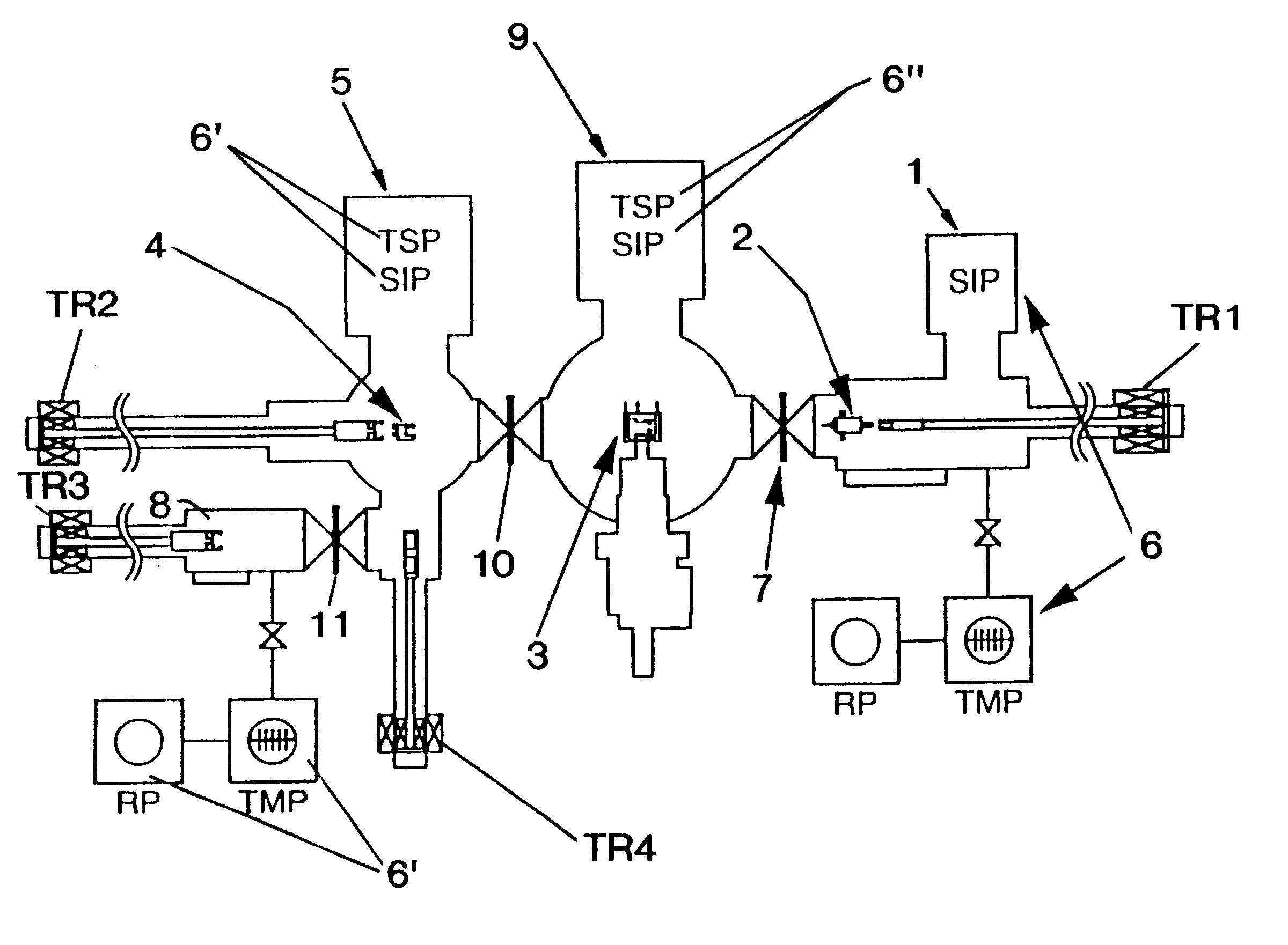
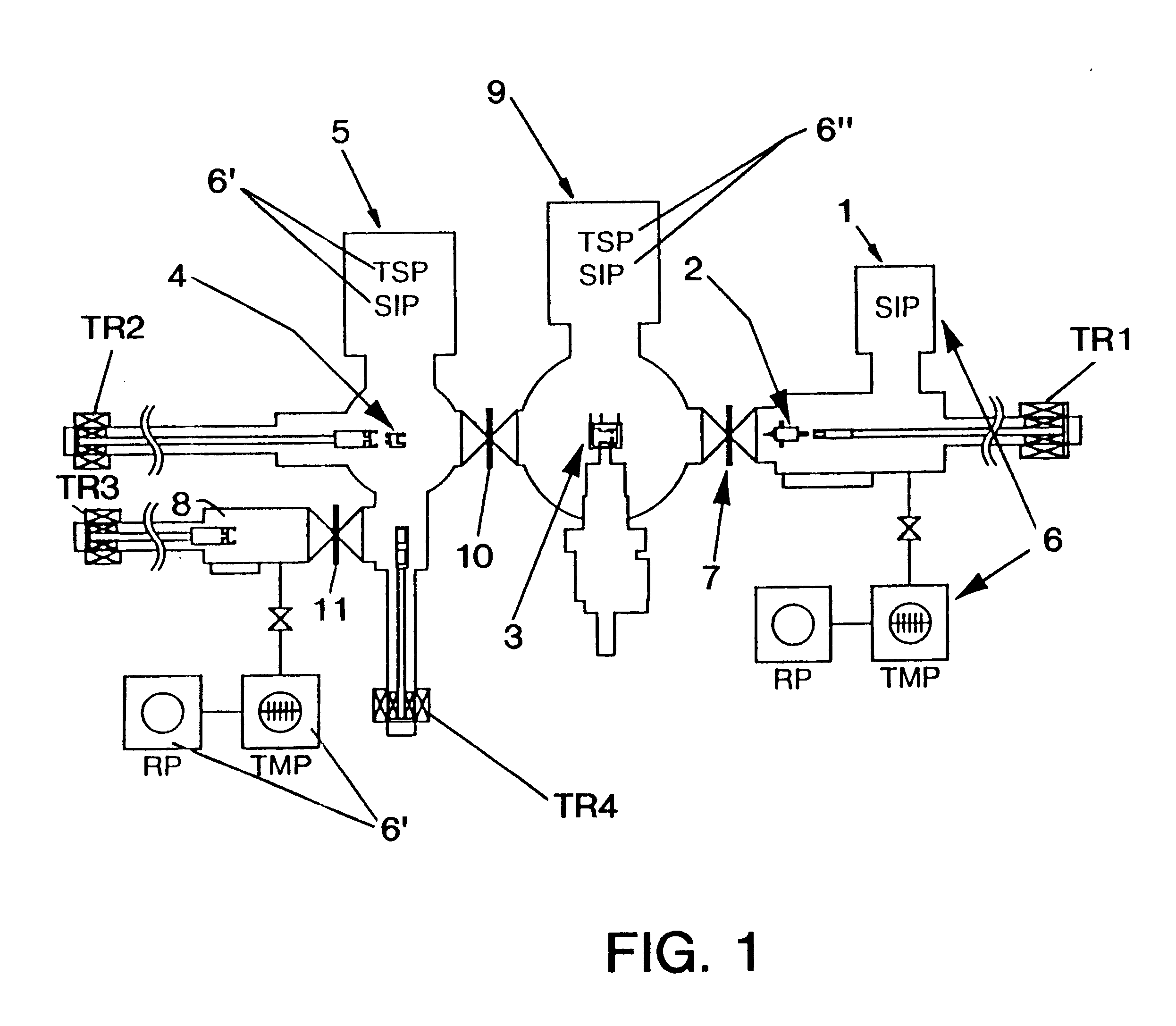
Electron microscope chamber 9 is ultra highly vacuumed (2.times.10.sup.-8 Pa) by means of ultra high vacuum exhausting system 6". STM contained in STM holder 2 is cleaned up in STM chamber 1 inside of which is ultra highly vacuumed (8.times.10.sup.-8 Pa) by means of ultra high vacuum exhausting system 6, then transferred to an observation stage 3 in electron microscope chamber 9 through valve 7 by TR1 and fixed. Electric voltage to be charged to a piezo element which controls X, Y and Z axes of STM is supplied by electric cords (not shown in drawings) which extends along with the transportation of STM holder 2 through valve 7.

Electric voltage-transferring distance characteristic of said element is 200 nm / 150V to X, Y direction and 600 nm / 150V to Z direction.

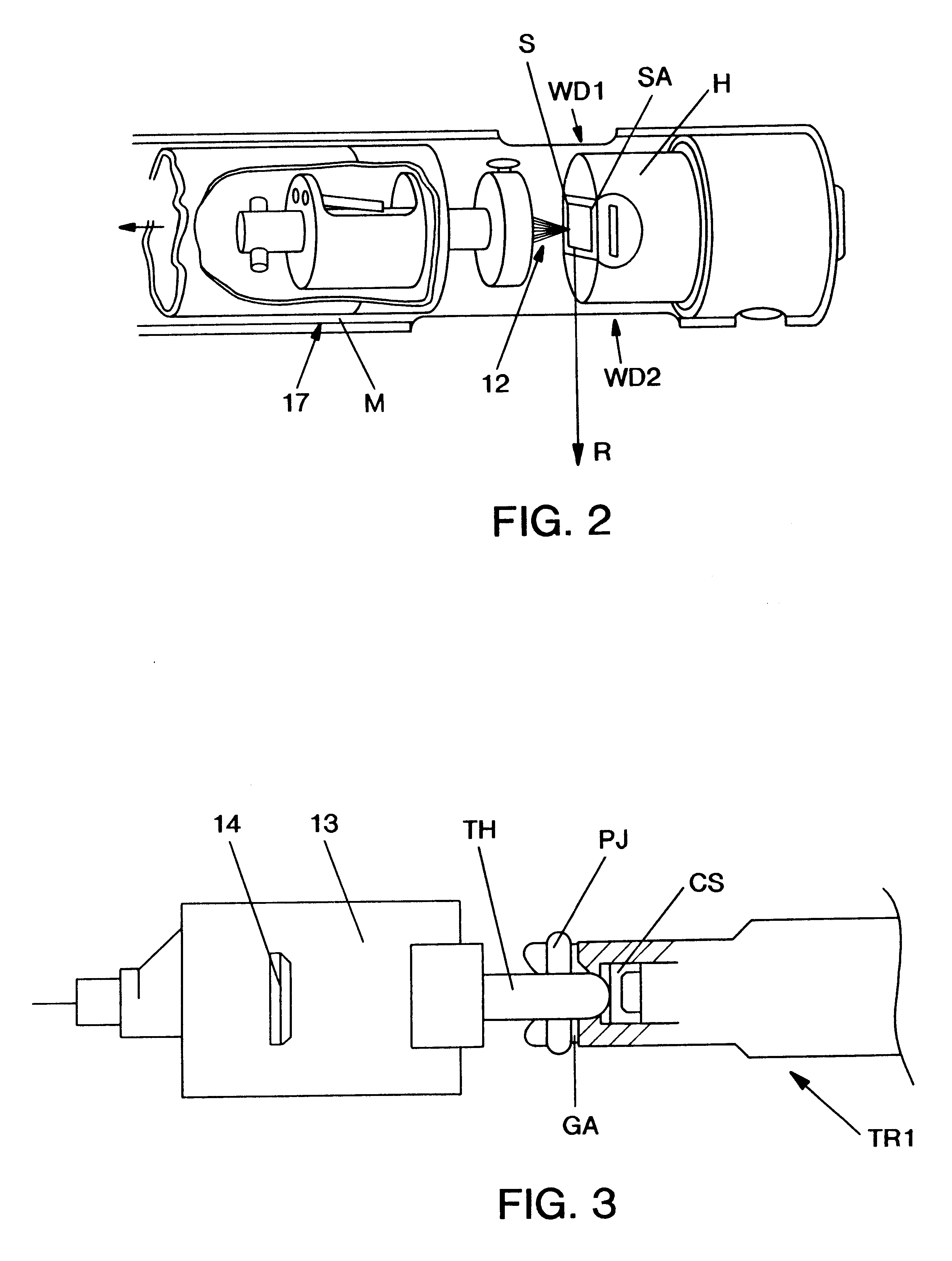
The specimen to be observed composed by gold vacuum evaporated copper line of 0.2 mm is set up to the notch part 18 of specimen holder 4, and ultra highly vacuumed (2.times.10.sup.-8 Pa) by means of ultra high vacuum exhausting s...


PUM

PropertyMeasurementUnit
heightaaaaaaaaaa
currentaaaaaaaaaa
transmission type electron microscopeaaaaaaaaaa

Abstract

The present invention is to provide a microscopic system by which a simultaneous observation at an ultra high vacuum condition by an electron microscope and by a scanning probe microscope is possible in an ultra high vacuum electron microscope chamber 9 equipped with an observation stage 3, to which an ultra high vacuum chamber 1 for a scanning probe microscope equipping with a scanning probe microscope holder 2 in which scanning probe microscope is contained and a specimen treatment chamber 5 possessing a specimen holder 4 on which a specimen is held are connected. Said each chamber of microscopic system can be separately exhausted to the ultra high vacuum level and the specimen holder and the scanning probe microscope holder can voluntarily be fixed to said observation stage and be removed from said observation stage.

Description

BACK GROUND OF THE INVENTIONThe present invention relates to a microscopic system which can combine an electron microscope and a scanning probe microscope, especially a scanning tunneling microscope, by which it becomes possible to make a simultaneous observation of a specimen by mentioned two different types of microscope in ultra high vacuum condition.DESCRIPTION OF THE PRIOR ARTIn general, as a method to install a scanning tunneling microscope (hereinafter, shortened to STM), the method disclosed in Ultra microscopy 48 (1993) 433 to 444 is well-known.The conventional microscopic system which observes a specimen simultaneously by electron microscope and scanning tunneling microscope is shown in FIG. 2. As clearly understood from FIG. 2, the system has a construction which is characterized by a specimen holder H and a scanning tunneling microscope M in one body in a cylindrical electron microscope holder 17 having a window (WD1) which allows an electronic beam to pass through and a...

Claims


Application Information

Patent Timeline
Patent Type & Authority Patents(United States)
IPC IPC(8): G01N27/00G01N13/10G01N13/12G01N37/00G21K5/10H01J37/28G01Q30/02G01Q30/16G01Q60/10
CPCB82Y35/00G01Q30/02H01J2237/204H01J2237/28Y10S977/852Y10S977/86Y10S977/871Y10S977/864
Inventor OHNISHI, HIDEAKIKONDO, YUKIHITOTAKAYANAGI, KUNIO
Owner JEOL LTD
Why Eureka
Try Eureka