Receiver, transmitter-receiver, and communication method

a communication method and receiver technology, applied in the field of receivers and transmitters, can solve the problems of inability to accurately restore transmission information bit series, high complexity of receiver structures, and inability to accurately perform the estimation of maximum likelihood series by the viterbi decoding circuit 17

Inactive Publication Date: 2001-06-05
SONY CORP
View PDF3 Cites 34 Cited by
  • Summary
  • Abstract
  • Description
  • Claims
  • Application Information

AI Technical Summary

Problems solved by technology

Therefore, influences caused in a transmission line are eliminated by performing convolution multiplication in a time domain by an equivalent circuit comprising an equalizer, resulting in highly complicated structures of the receivers.
Therefore, there are problems that maximum-likelihood series estimation by the Viterbi decoding circuit 17 cannot be accurately performed, and transmitted information bit series cannot be accurately restored.

Method used


Image

  • Receiver, transmitter-receiver, and communication method
  • Receiver, transmitter-receiver, and communication method
  • Receiver, transmitter-receiver, and communication method

Examples


Embodiment Construction

In the accompanying drawings:

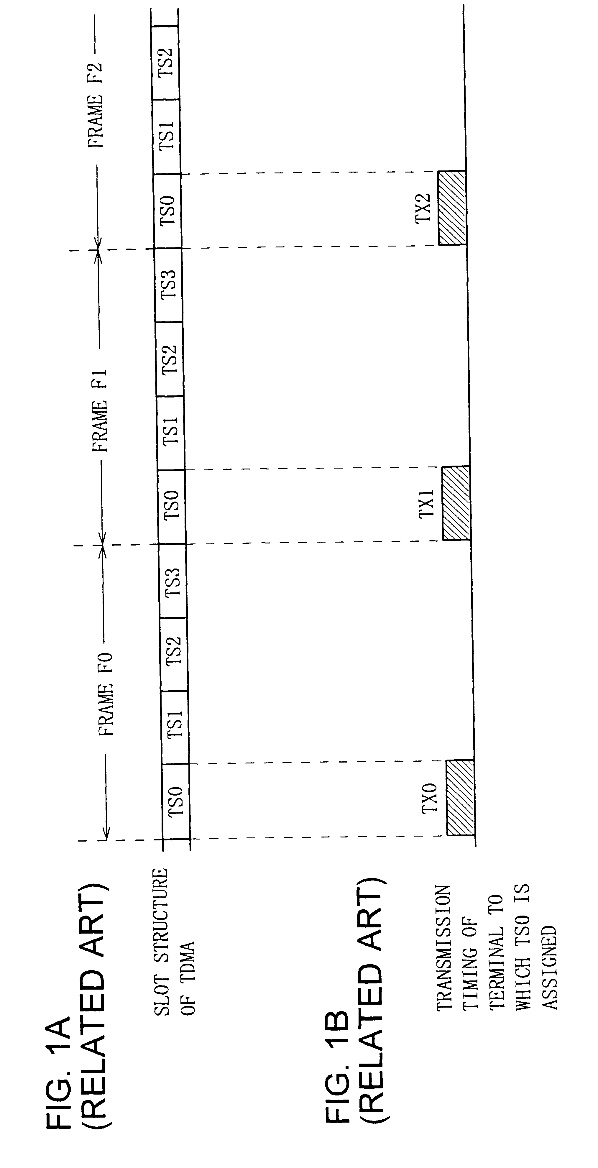
FIGS. 1A and 1B are schematic diagrams for explaining the theory of TDMA system;

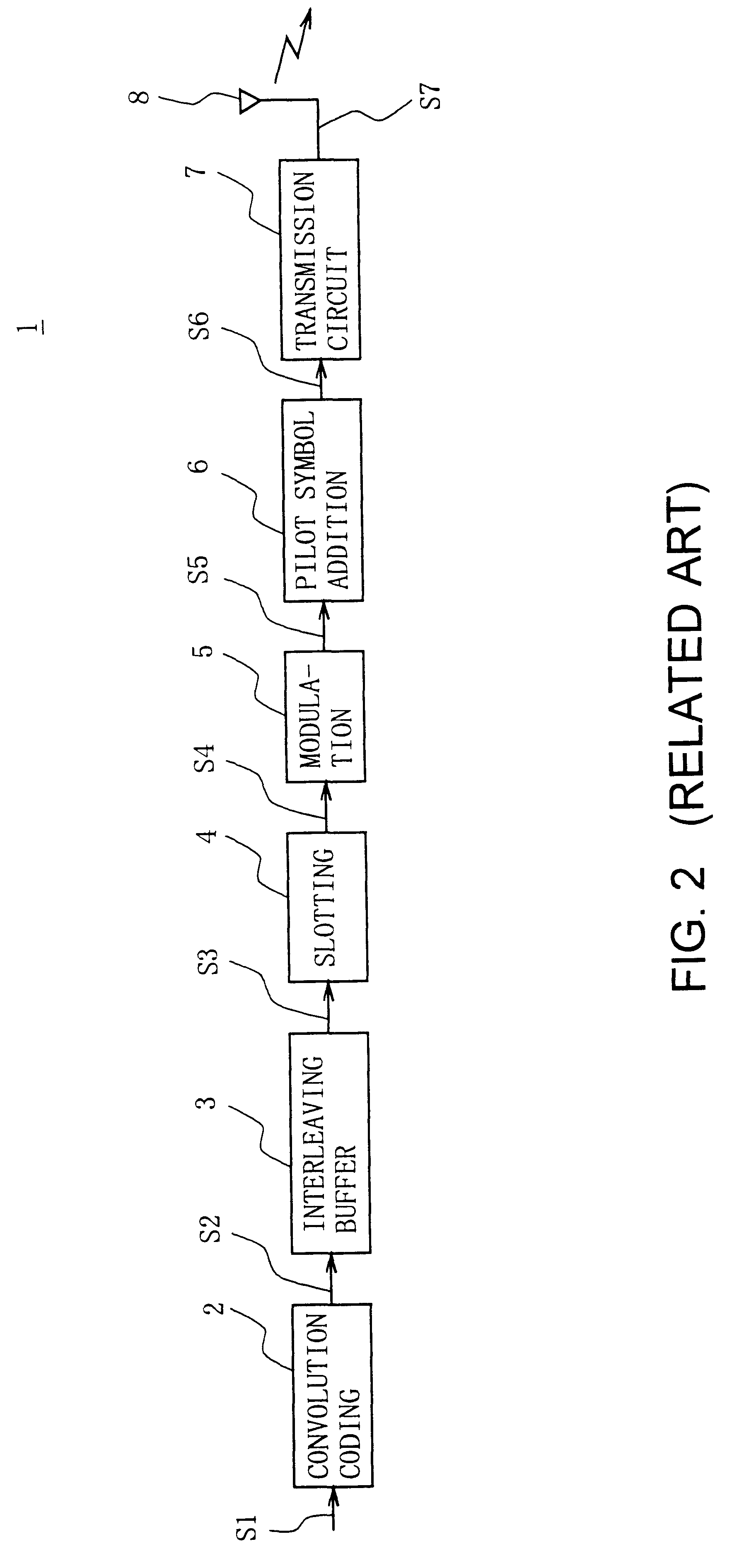
FIG. 2 is a block diagram showing the structure of a conventional transmitter;

FIG. 3 is a block diagram showing the structure of a conventional receiver;

FIG. 4 is a schematic diagram showing the arrangement of conventional pilot symbols;

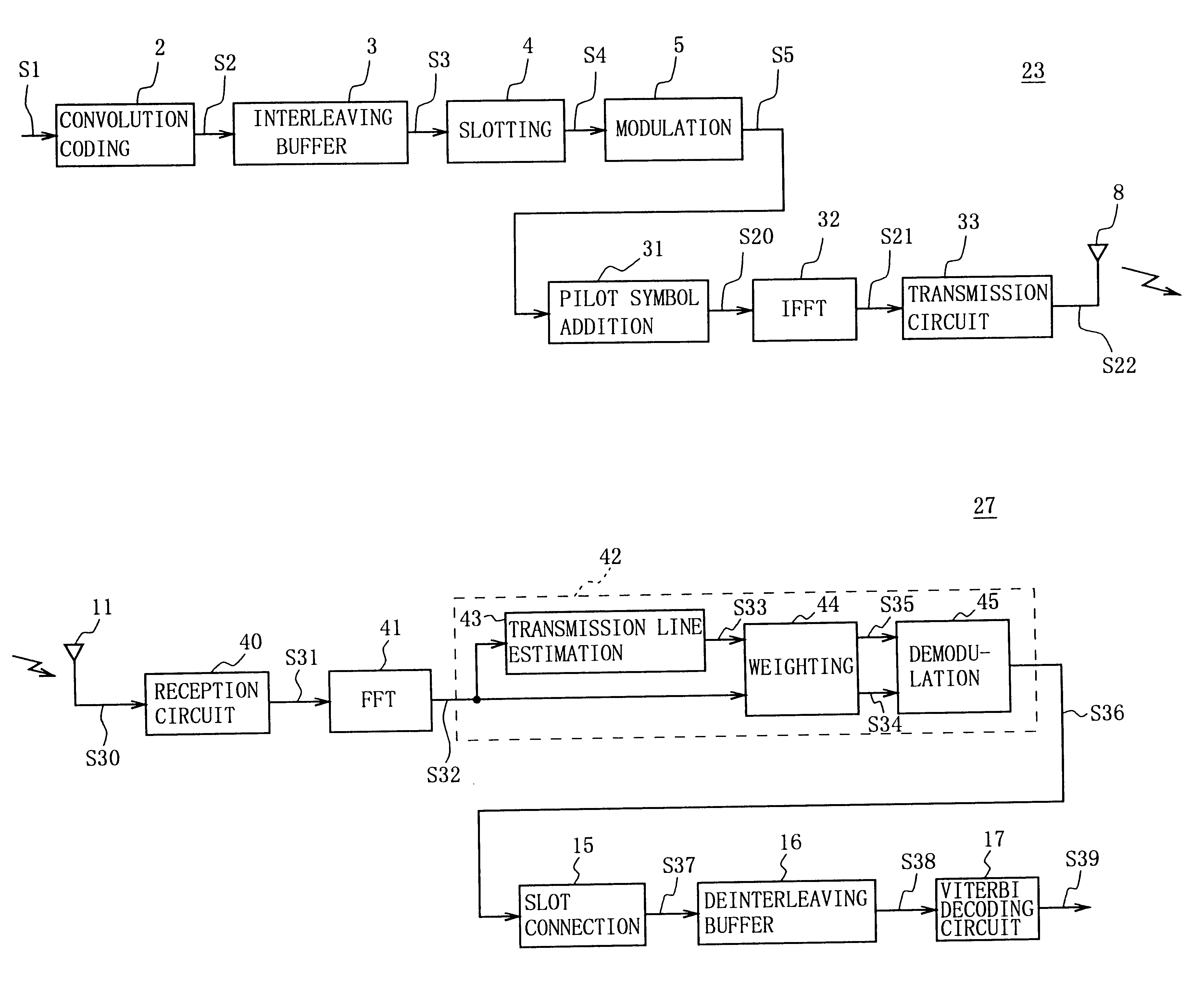
FIG. 5 is a block diagram showing the structure of the radio communication system of an embodiment of the present invention;

FIG. 6 is a block diagram showing the structure of a transmitter of the radio communication system in FIG. 5;

FIG. 7 is a signal point arrangement diagram for explaining the theory of QPSK modulation;

FIG. 8 is a signal point arrangement diagram for explaining the theory of 8 PSK modulation;

FIG. 9 is a signal point arrangement diagram for explaining the theory of 16 QAM modulation;

FIG. 10 is a signal point arrangement diagram for explaining the theory of 64 QAM modulation;

FIG. 11 is a schematic diagram for explaining the ar...


PUM


Abstract

A receiver restores a transmitted information bit series accurately by performing maximum-likelihood series estimation. The operation of the receiver includes estimating characteristics of a transmission line for each symbol based on the amplitude and phases of pilot symbols which are extracted from reception symbol groups, calculating weighting factors showing the reliability of the transmission line in symbols based on the estimation result and the reception symbol groups, multiplying each symbol of information symbol groups which are extracted from the reception symbol groups by the weighting factors to reflect the transmission-line reliability in symbols, and restoring an information bit series by applying maximum-likelihood series estimation to coded bit groups restored from the information symbol groups on which the reliability is reflected.

Description

1. Field of the InventionThe present invention relates to a receiver, a transmitter-receiver, and a communication method, and is suitably applied to, for example, a radio communication system such as a portable telephone system.2. Description of the Related ArtIn a radio communication system, including so-called cellular system, an area for providing communication services is divided into cells of prescribed sizes: in each of the cells a base station as a fixed radio station is located, and a portable telephone serving as a mobile radio station radio-communicates with the base station in the cell in which the telephone exists. Various systems are proposed for the communication systems between a portable telephone and a base station, and a typical one is a time division multiple connection system referred to as a time division multiple access (TDMA) system.As shown in FIGS. 1A and 1B, for example, in the TDMA system, a predetermined frequency channel is temporally partitioned into fr...

Claims


Application Information

Patent Timeline
Patent Type & Authority Patents(United States)
IPC IPC(8): H04L25/02H04L27/26H04L25/06H03M13/23H04L1/00H04L27/34H04L27/18
CPCH04L25/0228H04L25/067H04L27/2649H04L27/2626H04L27/265H04L27/2628H04L27/26134H04L27/36H04L27/38
Inventor SAKODA, KAZUYUKISUZUKI, MITSUHIRO
Owner SONY CORP
Why Eureka
Try Eureka