System for improving coalbed gas production

a coalbed gas and gas production technology, applied in the direction of drilling casings, drilling pipes, borehole/well accessories, etc., can solve the problems of inconvenient and costly water handling, and achieve the effect of prohibitively expensive use, and reducing the cost of coalbed gas production

Inactive Publication Date: 2001-06-12
THE UNIVERSITY OF WYOMING RESEARCH CORPORATION DBA WESTERN RESEARCH INSTITUTE
View PDF20 Cites 192 Cited by
  • Summary
  • Abstract
  • Description
  • Claims
  • Application Information

AI Technical Summary

Benefits of technology

Accordingly, the broad goal of the instant invention to increase coalbed gas recovery by stimulation of the coalbed formation. The invention improves on the previously mentioned ECBM recovery techniques. The present invention comprises a variety of coalbed stimulation techniques which are applied to coalbed methane production wells. The techniques serve to displace and confine water, alter the permeability of coalbed fracture systems, establish optimal coalbed stimulation gas amounts and coalbed gas removal rates, and as a result operate to limit water production rates in water-saturated coalbeds and reduce stimulation gas content in produced coalbed gas. The methods are simple, economical and time efficient. Naturally, as a result of these several different and potentially independent aspects of the invention, the objects of the invention are quite varied.
Another object of the invention is to reduce the cost of coalbed gas production. Most conventional coalbed gas stimulation techniques utilize continuous high pressure injection of stimulation gas during the production of coalbed gas. Additionally, many techniques utilize purified gas which necessitates fractionation of atmospheric gas. This necessitates the long term use of expensive multistage gas compressors and fractionation equipment. Moreover, many techniques also require separate injection wells and production wells and then subsequent purification of the produced coalbed gas. As such, these techniques may be prohibitively expensive to use. The instant invention, eliminates many of these expensive features and steps allowing coalbed gas to be produced at a considerably lower cost.

Problems solved by technology

This practice leads to a variety of problems with water handling and contamination of the coalbed gas produced.
Water handling as mentioned above is both costly and inconvenient.

Method used


Image

  • System for improving coalbed gas production
  • System for improving coalbed gas production
  • System for improving coalbed gas production

Examples


Embodiment Construction

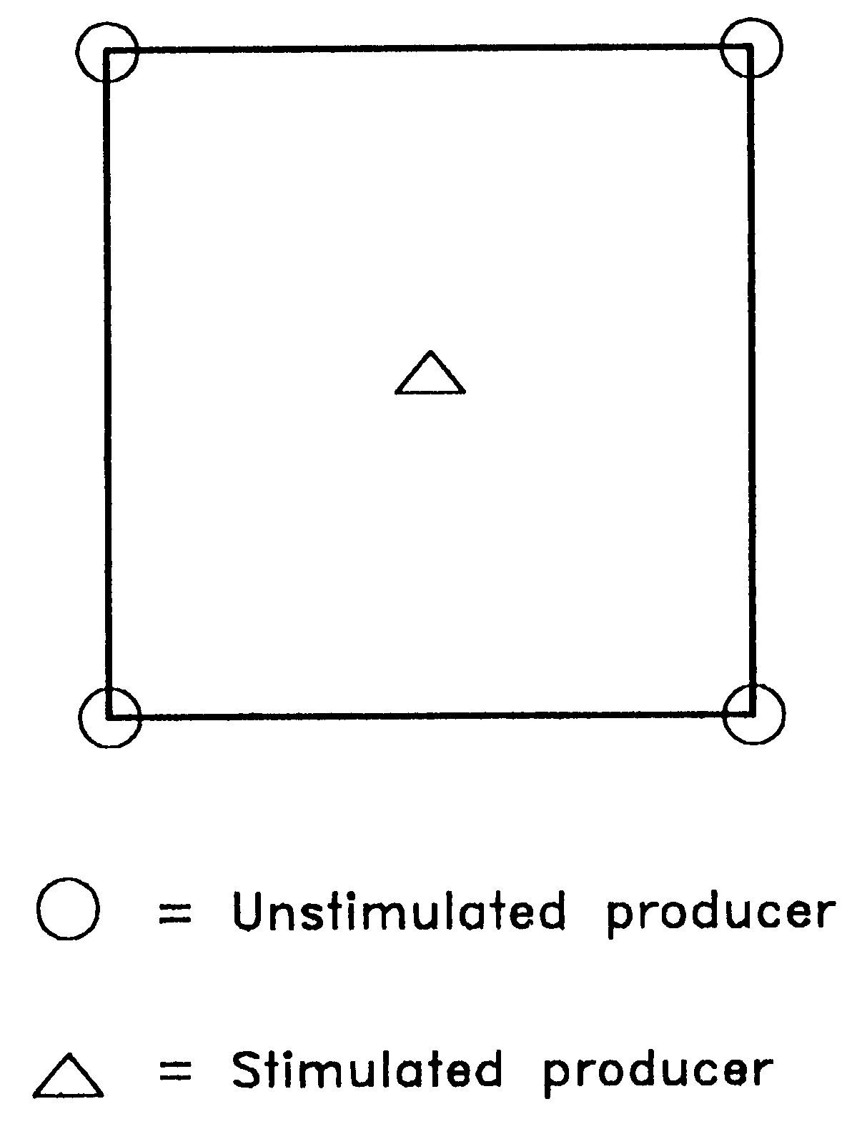
The following examples of both apparatus and methods for coalbed gas reservoir simulation are representative and do not limit the possible scenarios and variations of using this invention. A stimulation gas is applied to a production well located within a five-spot repeated pattern of producers on 320-acre spacings as shown in FIG. 7. The coalbed is fully water-saturated and has not been previously produced. The permeability of the coalbed is 1 Darcy, and its depth is 700 ft. A stimulation of the coalbed reservoir is performed by injecting 60 thousand standard cubic feet per day for 10 days. The producer is subsequently placed on production for the remainder of one year. The cumulative coalbed methane production as a function of time is shown in FIG. 8. Also shown in FIG. 8 is the cumulative coalbed methane production that results from a conventional gas depletion procedure. The stimulated well yields a 30-fold increase in cumulative production compared to the conventionally produce...


PUM


Abstract

A method of stimulating coalbed methane production by injecting gas into a producer and subsequently placing the producer back on production is described. A decrease in water production may also result. The increase in gas production and decrease in water production may result from: (1) the displacement of water from the producer by gas; (2) the establishment of a mobile gas saturation at an extended distance into the coalbed, extending outward from the producer; and (3) the reduction in coalbed methane partial pressure between the coal matrix and the coal's cleat system.

Description

Generally, this invention relates to the improved production of coalbed gas from substantially solid subterranean formations including coalbeds. Specifically, this invention relates to the use of a stimulation gas to manipulate the physical and chemical properties of such subterranean formations and to increasing the quantity, quality and rate of production of coalbed gases associated with such subterranean formations.A significant quantity of coalbed gas is physically bound (or sorbed) within coalbeds. This coalbed gas, which was formed during the conversion of vegetable material into coal, consists primarily of methane. Because it is primarily methane, coal gas is commonly termed coalbed methane. Typically, more than 95% of the coalbed methane is physically bound (adsorbed) onto the surface of the coalbed matrix.Coal may be characterized as having a dual porosity character, which consists of micropores and macropores. The micropore system is contained within the coal matrix. The m...

Claims


Application Information

Patent Timeline
Patent Type & Authority Patents(United States)
IPC IPC(8): E21B43/00
CPCE21B43/006
Inventor MONES, CHARLES G.
Owner THE UNIVERSITY OF WYOMING RESEARCH CORPORATION DBA WESTERN RESEARCH INSTITUTE
Why Eureka
Try Eureka