Position detector

a detector and position technology, applied in the field of position sensors, can solve the problems of system failure inability to operate in pulse-echo mode of operation, and inability to detect position errors

Inactive Publication Date: 2001-06-19
SINNAPTIX
View PDF73 Cites 166 Cited by
  • Summary
  • Abstract
  • Description
  • Claims
  • Application Information

AI Technical Summary

Problems solved by technology

However, the use of the conductive screen in place of the resonator has the disadvantages that the output signal levels are much smaller and that the system cannot be operated in a pulse-echo mode of operation, in which a short burst of excitation current is applied to the excitation winding and then, after the excitation current has ended, detecting and processing the signals induced in the sensor coils.
A problem common to all of these known position sensors is that a positional error is introduced into the measurements if the moveable member is tilted relative to the other member.
However, sometimes this is not possible.
However, this type of system suffers from the problem that it requires a large number of excitation coils, which must be individually energised, and a large number of sensor coils, which must be individually monitored for each energised excitation coil.
In particular, for high accuracy, a large number of excitation and sense coils are required, however, as the number of excitation coils and sensor coils increases, the system's response time decreases.

Method used


Image

  • Position detector
  • Position detector
  • Position detector

Examples


Embodiment Construction

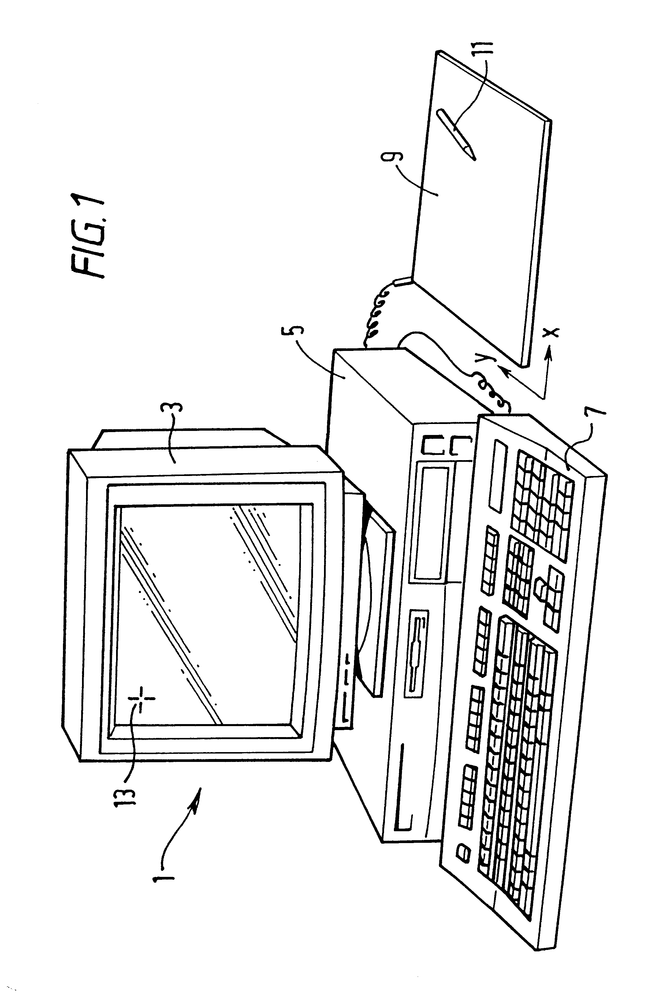
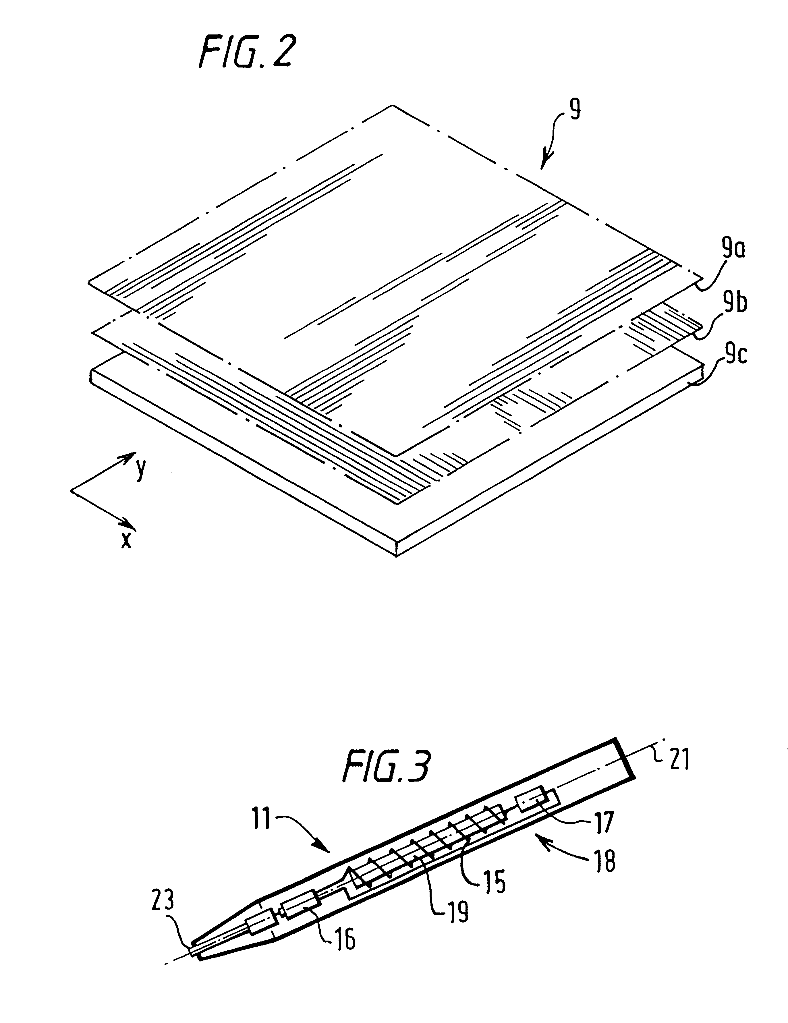
FIG. 1 schematically shows a computer system 1 having a display 3, a main processing unit 5, a keyboard 7, an X-Y digitising tablet 9 and a stylus 11. The X-Y digitising system senses the current X-Y position of the stylus 11 over the tablet 9 and uses the sensed position to control the location of a cursor 13 on the display 3. FIG. 2 schematically shows an exploded view of the digitising tablet 9. As shown, the digitising tablet comprises a first group of windings 9-a, a second group of windings 9-b and a base portion 9-c for supporting the two groups of windings 9-a and 9-b. The group of windings 9-a is used for determining the X coordinate position of the stylus 11 and the group of windings 9-b are used for determining the Y coordinate position of the stylus 11.

FIG. 3 shows in more detail the form of the stylus 11 shown in FIG. 1. As shown, the stylus 11 comprises a coil 15 which is connected in series, via a switch 16, to a capacitor 17 to form a resonant circuit, generally indi...


PUM


Abstract

A position detector is provided for detecting the relative movement of first and second members which are mounted for relative movement along a measuring path. One of the members comprises a magnetic field generator for generating a magnetic field and the other member comprises first and second conductors which are inductively coupled to said magnetic field generator. The arrangement of the first and second conductors and the magnetic field generator is such that output signals are generated in a first and second receive circuits whose position varies with the relative movement between the two members. In addition to carrying information relating to the relative position between the two members, the signals induced in the receive circuits also comprise information defining the relative orientation of the two movable members, and by suitable processing of the received signals the relative orientation of the two members can also be determined. In a preferred form of the invention, the system operates to define the relative position and orientation of the two movable members in first and second directions from which the relative orientation of the two members in a plane containing the two directions can be determined. The signals induced in the receive circuits can also be processed to give an indication of the gap between the two circuits and to provide an indication of the full relative orientation of the two members.

Description

1. Field of the InventionThe present invention relates to position sensors generally. The invention has particular although not exclusive relevance to non-contact linear and rotary position encoders. The invention is particularly suited for use in systems where the object whose position is being sensed can be tilted relative to the measurement direction.2. Related ArtMany types of non-contact linear and rotary position encoders have been proposed for generating signals indicative of the position of two relatively moveable members. Typically, one of the members carries one or more sensor coils and the other carries one or more magnetic field generators. The magnetic field generators and the sensor coils are arranged such that the amount of magnetic coupling between them varies as a function of the relative position between the two members. This can be achieved by, for example, designing the sensor coils so that their sensitivity to magnetic field varies in a predetermined manner alon...

Claims


Application Information

Patent Timeline
Patent Type & Authority Patents(United States)
IPC IPC(8): G01D5/12G01D5/20G06F3/033G06F3/041G06F3/046
CPCG01D5/2073G01D5/208G06F3/03545G06F3/041G06F3/046G06F2203/04101
Inventor ELY, DAVID T. E.JONES, ROSS P.ENGLAND, JAMES M. C.MCKINNON, ALEXANDER W.PETTIGREW, ROBERT M.DAMES, ANDREW N.HOWE, ANDREW R. L.
Owner SINNAPTIX
Why Eureka
Try Eureka