
Control module for a brake system for a semi-trailer

a control module and semi-trailer technology, applied in the direction of brake safety systems, vehicle components, braking systems, etc., can solve the problems of slowing down, driver can press too hard for the prevailing conditions, slowing down, etc., to achieve rapid reduction of brake pressure, better wheel control, and the effect of reducing the pressur

Inactive Publication Date: 2001-07-24
WABASH NATIONAL
View PDF6 Cites 30 Cited by
  • Summary
  • Abstract
  • Description
  • Claims
  • Application Information

AI Technical Summary

Benefits of technology

Another object of the present invention is to integrate a quick exhaust valve into the ACM for the rapid release of air from the system, and to periodically exhaust signal air to atmosphere, and to provide better release timing than a conventional check valve which would normally be incorporated into ABS.
Yet another object of the present invention is to provide a novel ABS which can be used with relay valves from any manufacturer and provides the brake system designer with additional flexibility in defining the brake system architecture.
Yet a further object of the present invention to provide the ability for a service technician to check the system for a malfunction.

Problems solved by technology

The slowing wheel also slows the vehicle because of friction between the tire and the road surface.
A disadvantage with conventional brake systems is that the driver can press too hard for the prevailing conditions, for example when driving on snow or wet asphalt.
The vehicle does slow down, but directional control is lost, and, depending on which wheels lock, and on the road conditions, the vehicle may spin.
This is not an easily accessible location.

Method used


Image

  • Control module for a brake system for a semi-trailer
  • Control module for a brake system for a semi-trailer
  • Control module for a brake system for a semi-trailer

Examples


second embodiment

Directing attention to the PCM 26 in FIG. 7, the PCM 26 includes a first 2-way solenoid valve 104 which is normally open, and a second 2-way solenoid valve 106 which is normally closed.

The first 2-way solenoid valve 104 has a housing having an inlet port 108 and an outlet port 110. A plurality of windings are housed within the housing and encircle a plunger which is biased away from the inlet port 108 by a spring and can be selectively moved against the inlet port 108 when the 2-way solenoid valve 104 is energized. In the non-energized position, the 2-way solenoid valve 104 is open such that the air signal can flow therethrough. That is, the inlet port 108 and outlet port 110 are open in that the plunger is not biased against the inlet port 108.

The second 2-way solenoid valve 106 has a housing having an inlet port 112 and an outlet port 114. A plurality of windings are housed within the housing and encircle a plunger which is biased against the outlet port 114 by a spring and can be...

first embodiment

The PCM 26 also includes a novel quick exhaust valve 82 which is integrated therein and is identical in structure to the quick exhaust valve 82 used in the PCM 26. Identical reference numerals are used to denote the elements of the quick exhaust valve 82.

A line 116 is connected to the supply port 60 and has a first branch line 116a connected to the inlet port 108 of the first 2-way solenoid valve 104 and a second branch line 116b connected to the inlet port 84 of the quick exhaust valve 82. A line 118 is connected to the outlet port 110 of the first 2-way solenoid valve 104, and has a first branch comprised of two lines 118a, 118b connected to the inlet port 112 of the second 2-way solenoid valve 106, has a second branch line 118c connected to the exhaust inlet port 86 of the quick exhaust valve 82, and a third branch line 118d connected to the delivery port 62 of the PCM. A line 120 is connected to the outlet port 114 of the second 2-way solenoid valve 106 and has a first branch li...

third embodiment

During normal braking using the PCM 26 shown in the third embodiment, the following steps are effected:

1. Signal air passes in the supply port 60 of the PCM 26, and travels along lines 152, 152a to the inlet port 130 of the non-energized normally open 2-way solenoid valve 122.

2. The signal air passes through the inlet port 130 of the 2-way solenoid valve 122, around the plunger and out the outlet port 132 of the 2-way solenoid valve 122.

3. The signal air passes along line 154 and through the inlet port 134 of the non-energized 3-way solenoid valve 124, around the plunger and out the outlet port 136.

4. The signal air then passes along lines 156, 156a, through the quick exhaust valve 128 by traveling in the inlet port 144, around the diaphragm and out the open two-way port 146, to the delivery port 62 of the PCM 26 and then to the relay valve 48.

The check valve 126 is not used during application of the brakes in normal braking. Pressure on the second port 142 side of the check valve 1...


PUM


Abstract

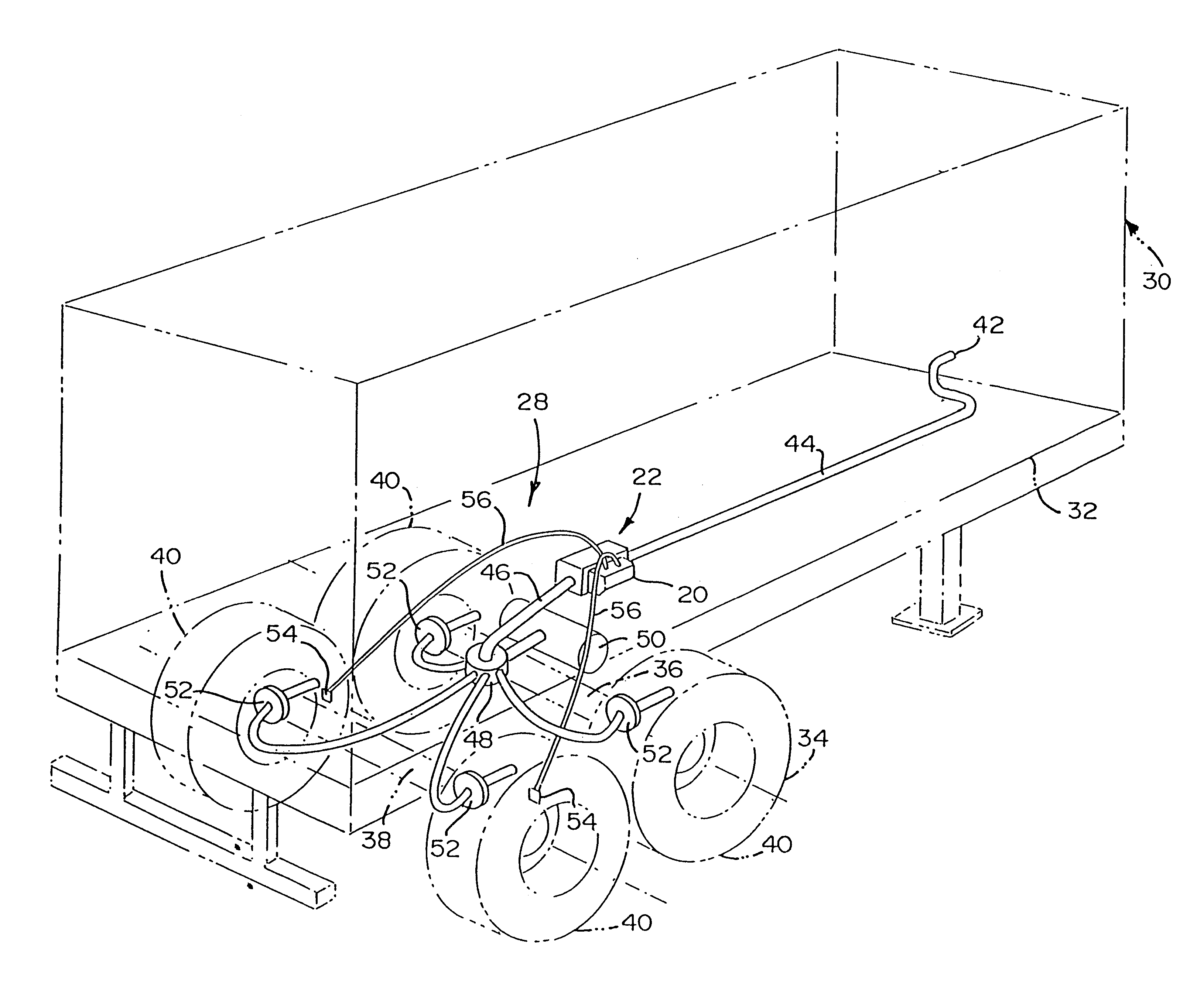
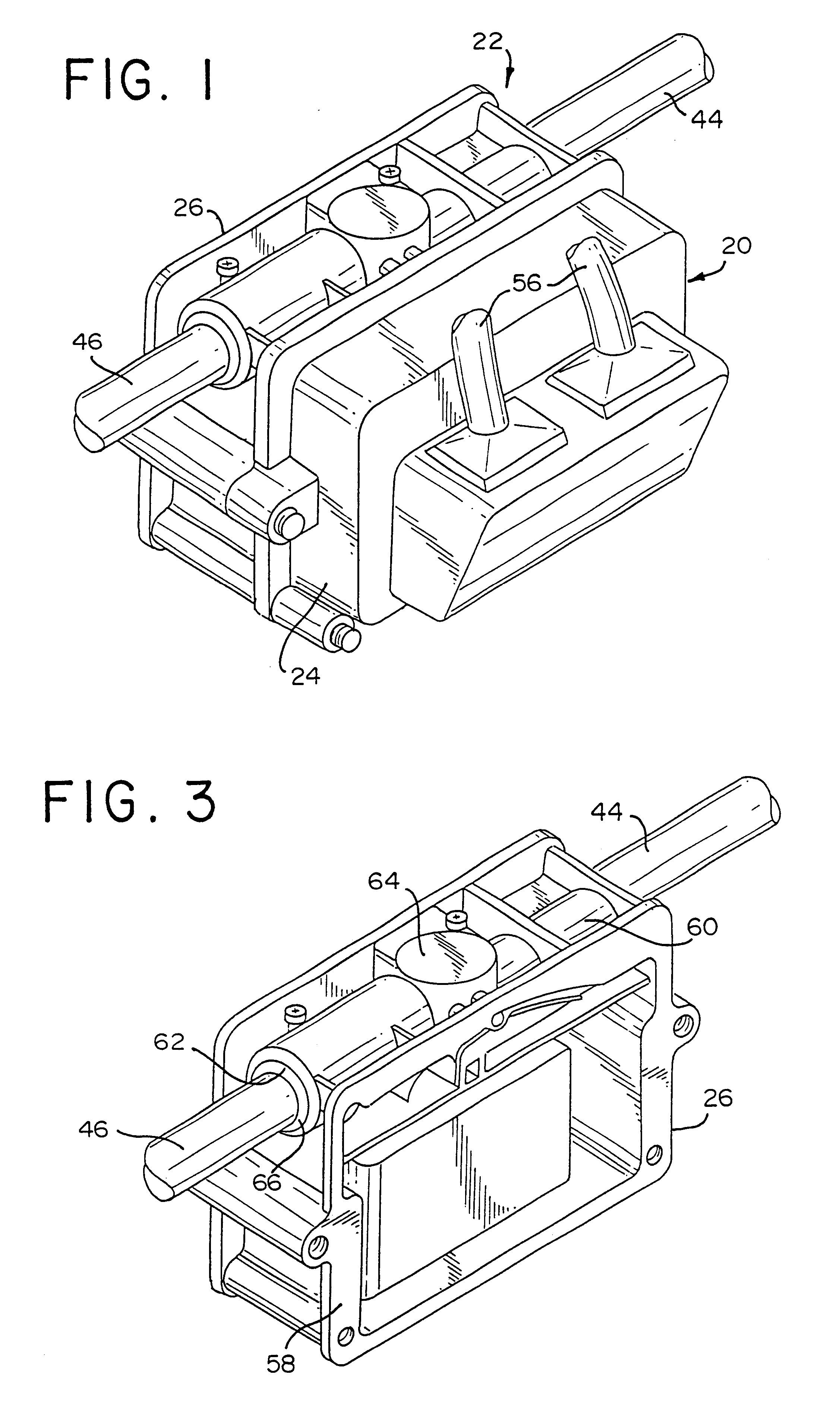
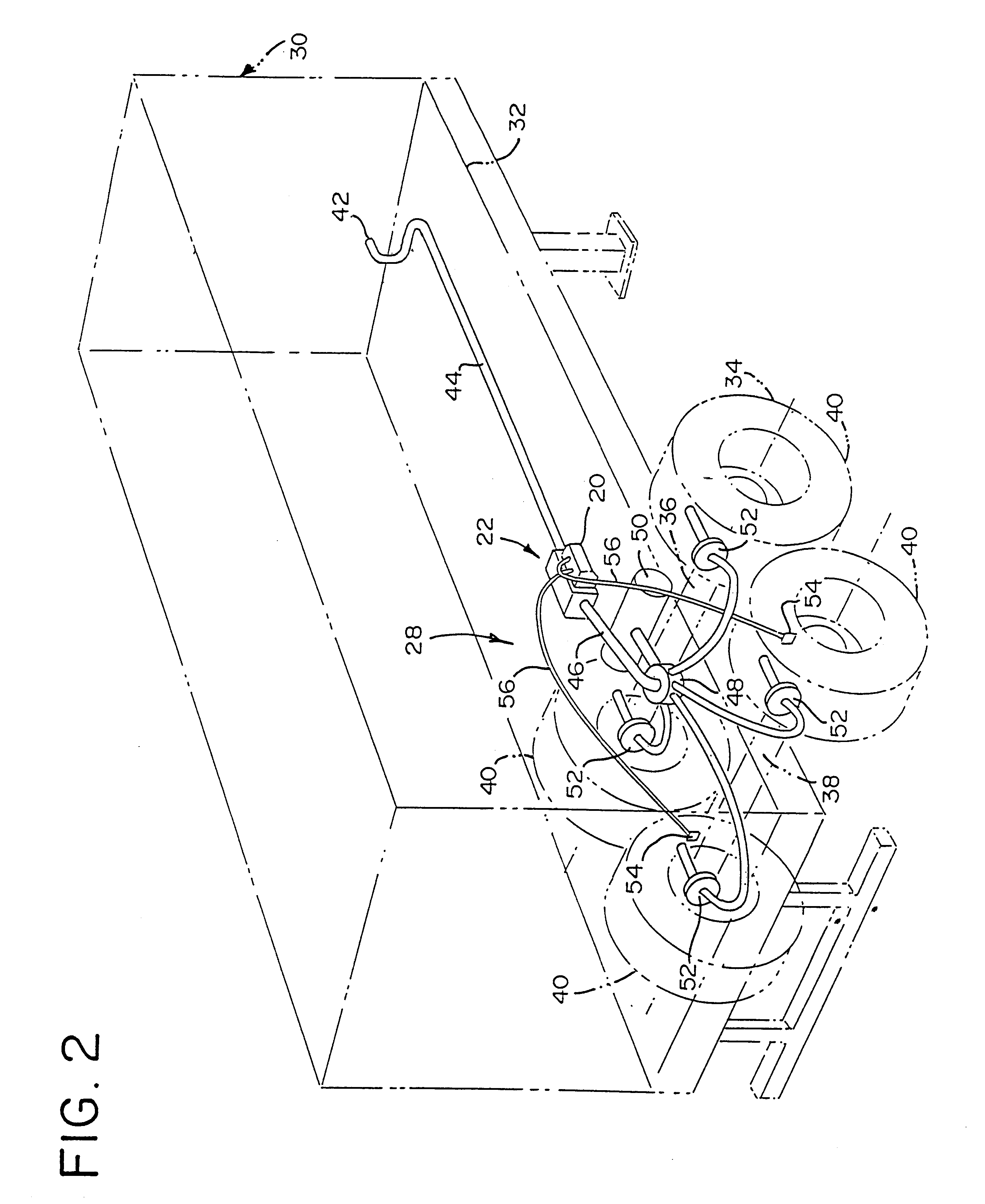
A brake system for an air braked trailer includes a first control line for transmitting air from a source, a second control line for transmitting air, a relay valve allowing air to flow therethrough, and a pneumatic control module (PCM) having structure for reducing pressure from an inlet port of the PCM to an outlet port of the PCM. The PCM is connected to the first control line and is solely connected to the relay valve by the second control line. The first and second control lines are capable of being decoupled from the PCM and being coupled to each other to remove the PCM from the system so that a technician can check the system. An exhaust valve is integrally connected with the PCM and is capable of exhausting air to atmosphere. When the system is used on trailer, the PCM is mounted away from the relay valve, and preferably forwardly of a forward axle of the trailer.

Description

This invention is generally directed to a brake system for heavy truck trailers which use an air-braked system, and specifically to an antilock brake system for such a trailer.In a conventional brake system without antilock brakes, when the driver presses the brake pedal, fluid is forced through conduits to the actual brake mechanism at each wheel. The fluid is pressurized and forces a stationary braking surface against a rotating surface which is attached to the wheel. This action slows the wheel through the effect of friction. The braking surfaces are the shoe linings for drum brakes and the pad linings for disk brakes. The rotating surfaces are, respectively, drums or rotors. The slowing wheel also slows the vehicle because of friction between the tire and the road surface. For hydraulic brakes, as used on all cars and smaller trucks, the working fluid is "brake fluid" which is an actual liquid. For large trucks, the working "fluid" is air, which is of course a mixture of gases.A...

Claims


Application Information

Patent Timeline
Patent Type & Authority Patents(United States)
IPC IPC(8): B60T13/68B60T13/24B60T13/26B60T17/18B60T8/32
CPCB60T8/323B60T17/18B60T13/683B60T13/263
Inventor EHRLICH, DONALD J.EHRLICH, RODNEY P.MCCANN, GERARD OWEN
Owner WABASH NATIONAL
Learn More