Method and combustor for combusting hydrogen

Inactive Publication Date: 2001-07-31
DAIMLER CHRYSLER AEROSPACE AIRBUS
View PDF17 Cites 72 Cited by
  • Summary
  • Abstract
  • Description
  • Claims
  • Application Information

AI Technical Summary

Benefits of technology

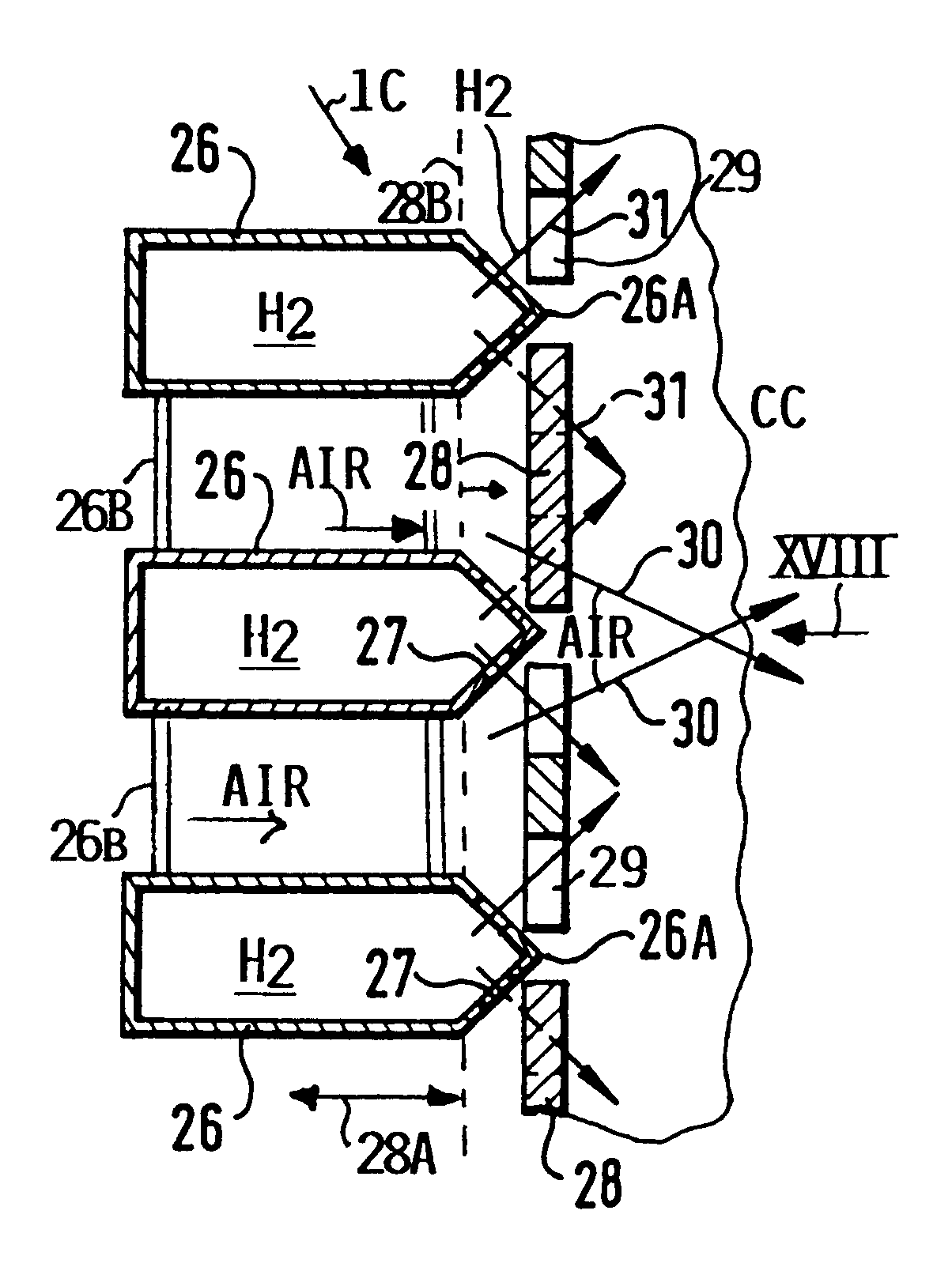
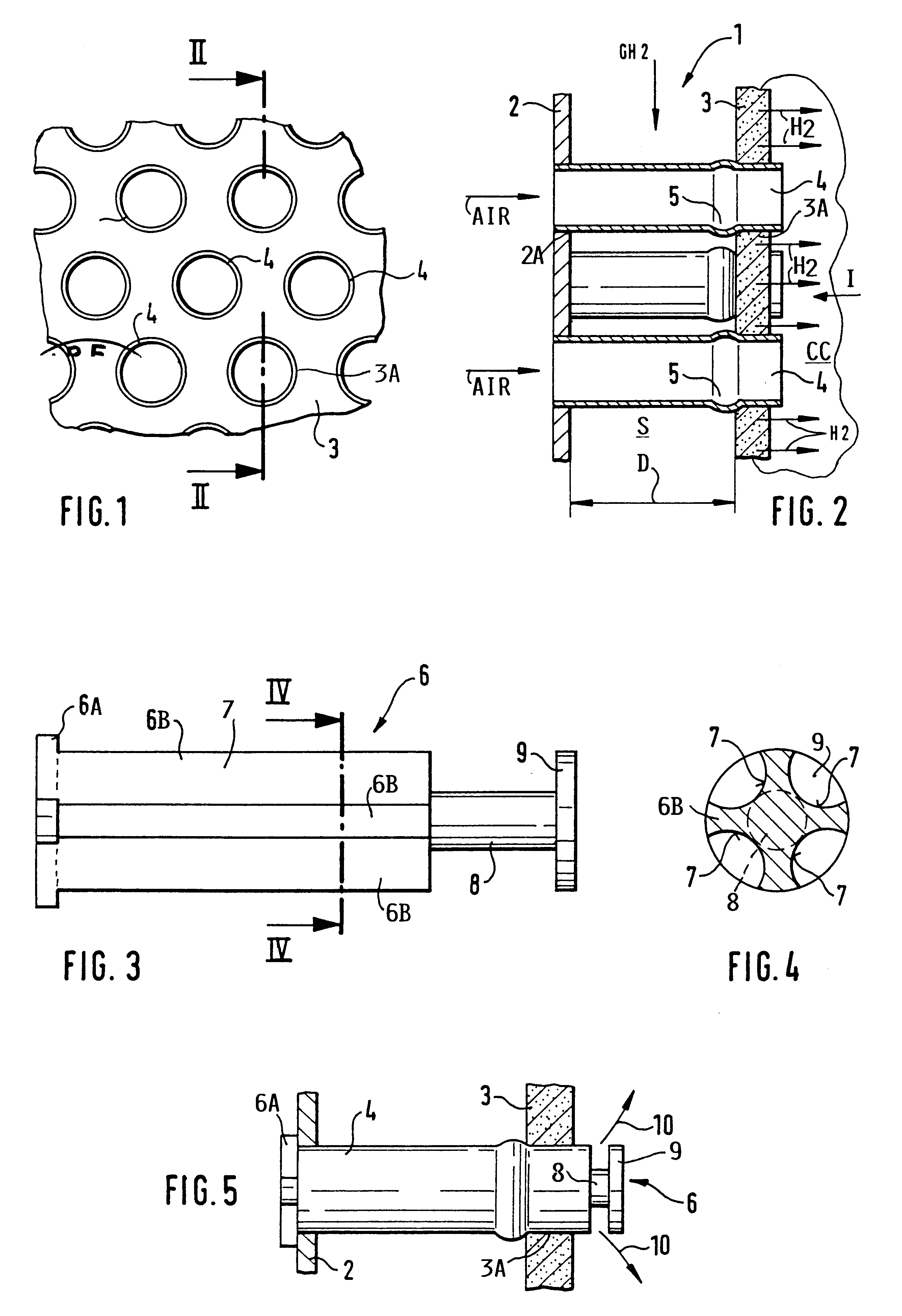
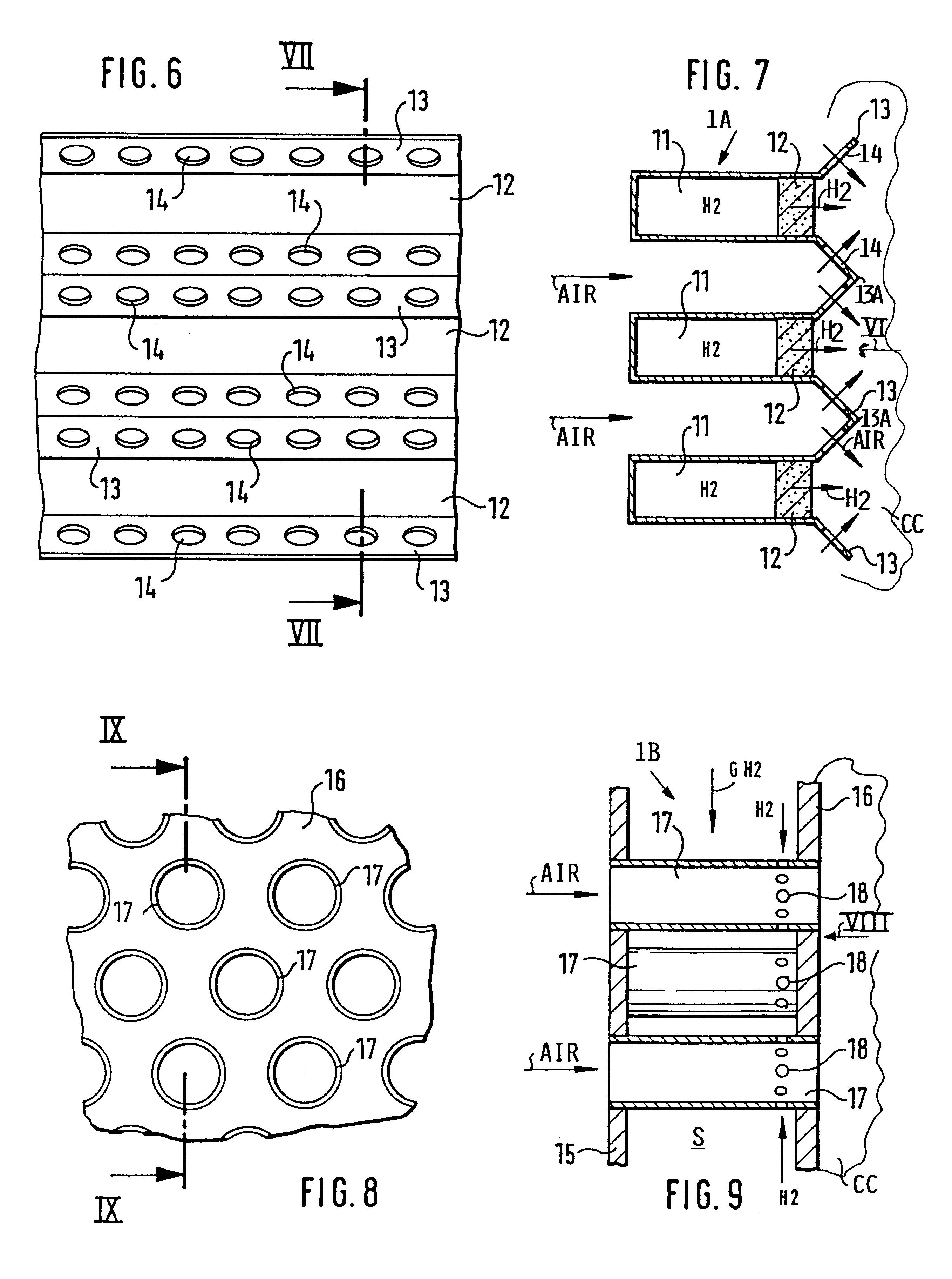
A combustor according to the invention combines the following features: a combustion chamber in which exhaust gas including nitrogen oxides NO.sub.x is produced during combustion, said combustor comprising a burner surface area facing into said combustion chamber (CC), a number of hydrogen fuel inlet through-holes in said combustor for feeding hydrogen jets into said combustion chamber, a plurality of air inlets in said combustor for feeding air jets into said combustion chamber, said fuel inlet through-holes and said air inlets being so positioned relative to each other and relative to said combustion chamber that a flow direction of said hydrogen jets and a flow direction of said air jets enclose a mixing angle for diffusive micromixing of hydrogen and air in said combustion chamber with a mixing intensity that depends on a pressure drop available in sai

Problems solved by technology

In spite of the advantages that are attained by the premixing with regard to the reduction of nitrogen oxides emissions in engine exhaust gases, there is a substantial drawback in such premixing in that flame flashbacks from the combustion chamber back into the premixing area can happen.
Such flame flashbacks are very dangerous.
A substantial risk of flashbacks, however, cannot be avoided by the teachings of Striebel et al. if the fuel is hydrogen having very large flame velocities.
The TRUD or Kusnetzov system has its limitations in further increasing the number of hydrogen injection nozzles, because the increased num

Method used


Image

  • Method and combustor for combusting hydrogen
  • Method and combustor for combusting hydrogen
  • Method and combustor for combusting hydrogen

Examples


Embodiment Construction

The invention will first be explained with reference to FIG. 24 which illustrates test results performed with a gas turbine engine model A 320 APUGTCP 36-300. FIG. 24 shows the content of NO.sub.x in cubic foot.times.10.sup.-6 per cubic foot of exhaust gas as a function of the flame density per square inch of the combustor surface facing into the combustion chamber. The tests were made under atmospheric conditions which means that the absolute Nox levels measured in the tests are based on atmospheric burner entrance conditions. The combustor had a surface area of 67.9 square inches facing into the combustion chamber. In its original conventional form the combustor had six air injection nozzles distributed over the combustor surface providing 0.088 diffusion flames per square inch. Tests were run with the conventional combustor using hydrogen fuel in one test and kerosene fuel in another test. The NO.sub.x content in the exhaust gas was the same for both fuels, namely as shown at poi...


PUM


Abstract

A plate burner for combusting hydrogen with air as an oxidizer forms a wall portion of a combustion chamber for example of a gas turbine. The plate burner is so constructed that air and hydrogen are separately guided to the downstream surface area facing into the combustion chamber for forming a large number of diffusive microcombustion flames, thus achieving a very low mixing scale simultaneously with a high nixing intensity. The number of diffusive micorcombustion flames is so selected that the NOx content in the exhaust gas from the combustion chamber is at the most 10x10-6 cubic foot per cubic foot of exhaust gas. The hydrogen enters the entrance area into the combustion chamber either through a porous wall, and air is injected into the hydrogen environment to form inverse diffusive microcombustion flames or the hydrogen is injected through a multitude of fine holes into high velocity air jets forming regular diffusion flames. In both instances, the formation of NOx in the exhaust gas during combustion is reduced to the above level or below.

Description

The invention relates to a method and burner or combustor for combusting hydrogen by diffusion combustion using air as an oxidizer. This method and combustor are especially useful in connection with gas turbine combustion chambers in aircraft engines.BACKGROUND INFORMATIONThe use of hydrogen (H.sub.2) as fuel for burners of all kinds, for example for combustors in combustion chambers of gas turbines, has the advantage of an especially high reactivity and thus an extraordinary large stability in the combustion. This stable combustion is achieved even if there is an excess air supply as is the case in the combustion chambers of gas turbines.Publications relating to combustion techniques by Heywood and Mikus show that a reduction in the formation of nitrogen oxides (NO.sub.x) can be achieved in combustion flames with a sufficiently high air excess if the mixing quality of air and fuel is increased. According to Heywood and Mikus, the NO.sub.x formation can be minimized by a completely ...

Claims


Application Information

Patent Timeline
IPC IPC(8): F23D14/46F23D14/00F23D14/70F23D14/20
CPCF23D14/20F23D14/70F23C2900/9901F23D2900/00012F23D2209/20
Inventor SUTTROP, FRIEDEMANN
Owner DAIMLER CHRYSLER AEROSPACE AIRBUS
Why Eureka
Try Eureka