Image processing device and still image pickup device, and method for processing image
a processing device and pickup device technology, applied in the field of image processing, can solve the problems of increased power consumption, inability to achieve high-speed continuous shooting, and inability to create high-definition reproduced images
- Summary
- Abstract
- Description
- Claims
- Application Information
AI Technical Summary
Benefits of technology
Problems solved by technology
Method used
Image
Examples
embodiment 1
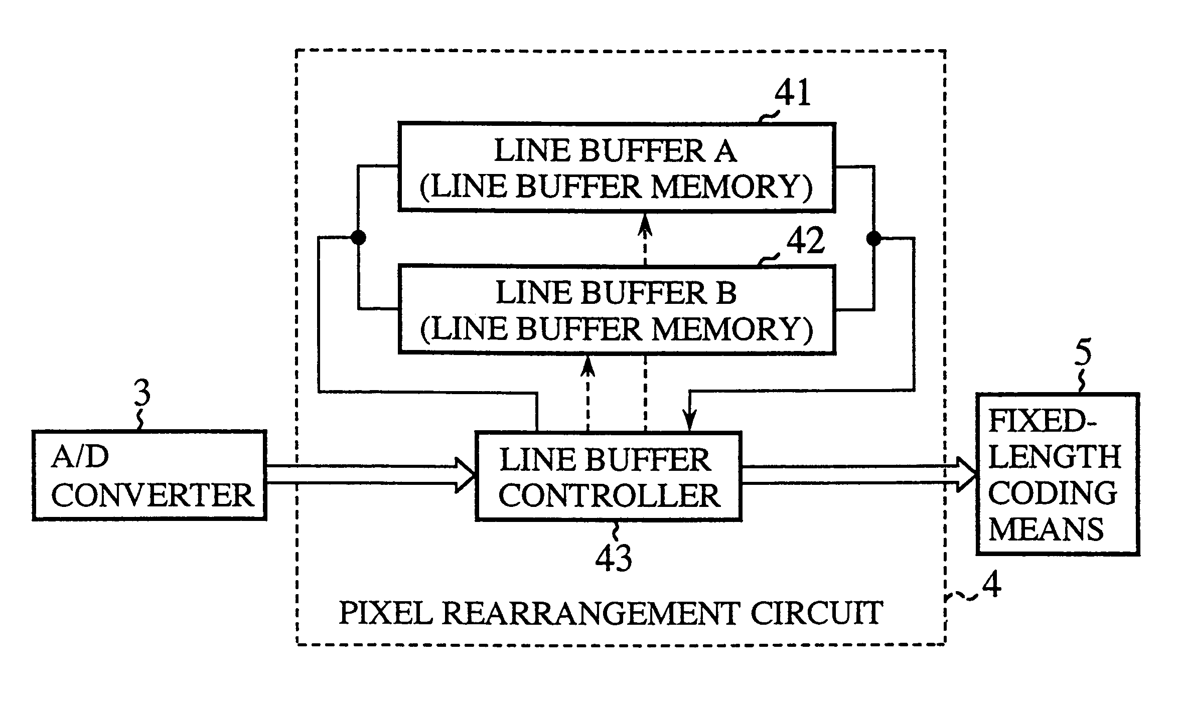
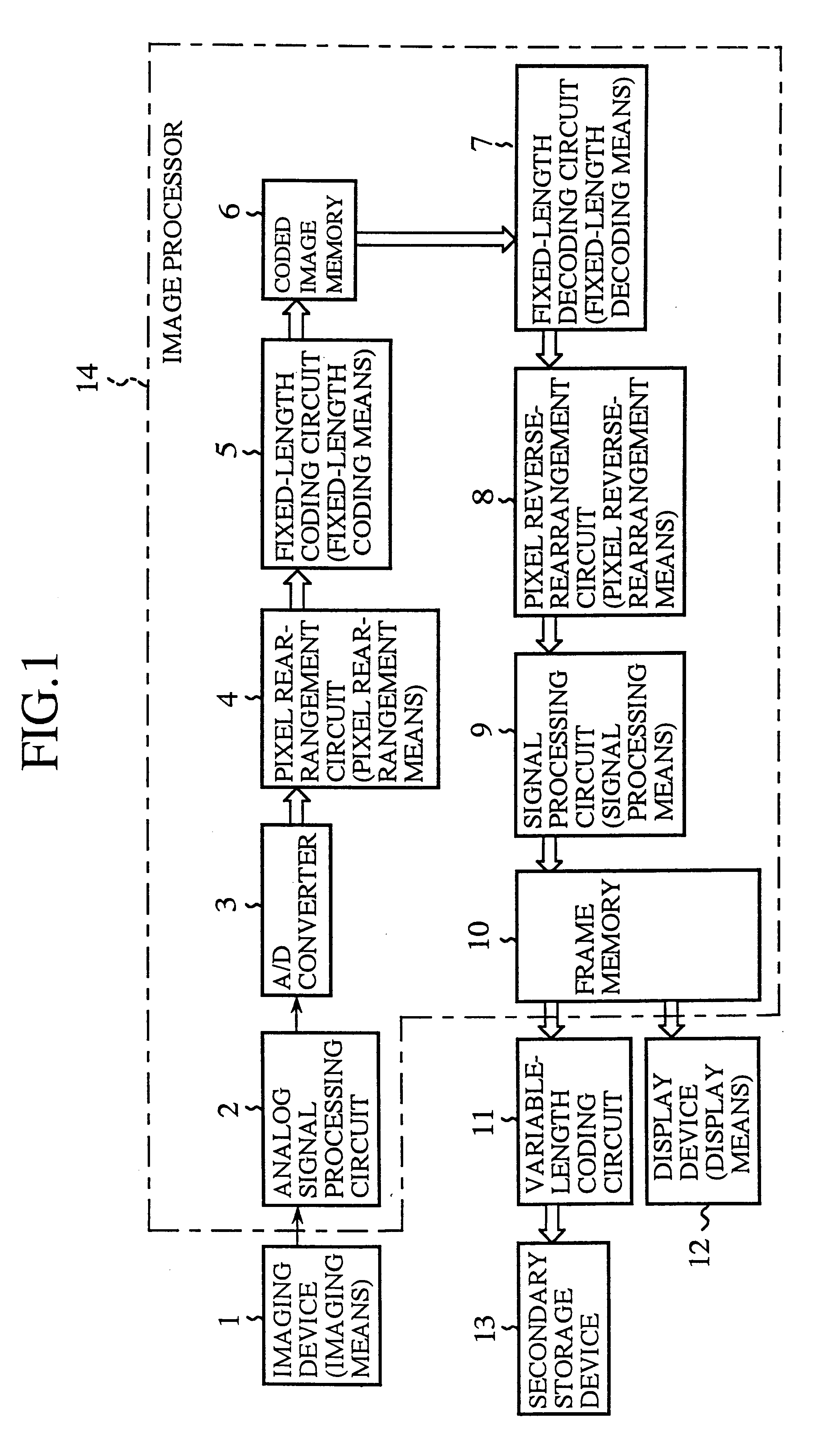
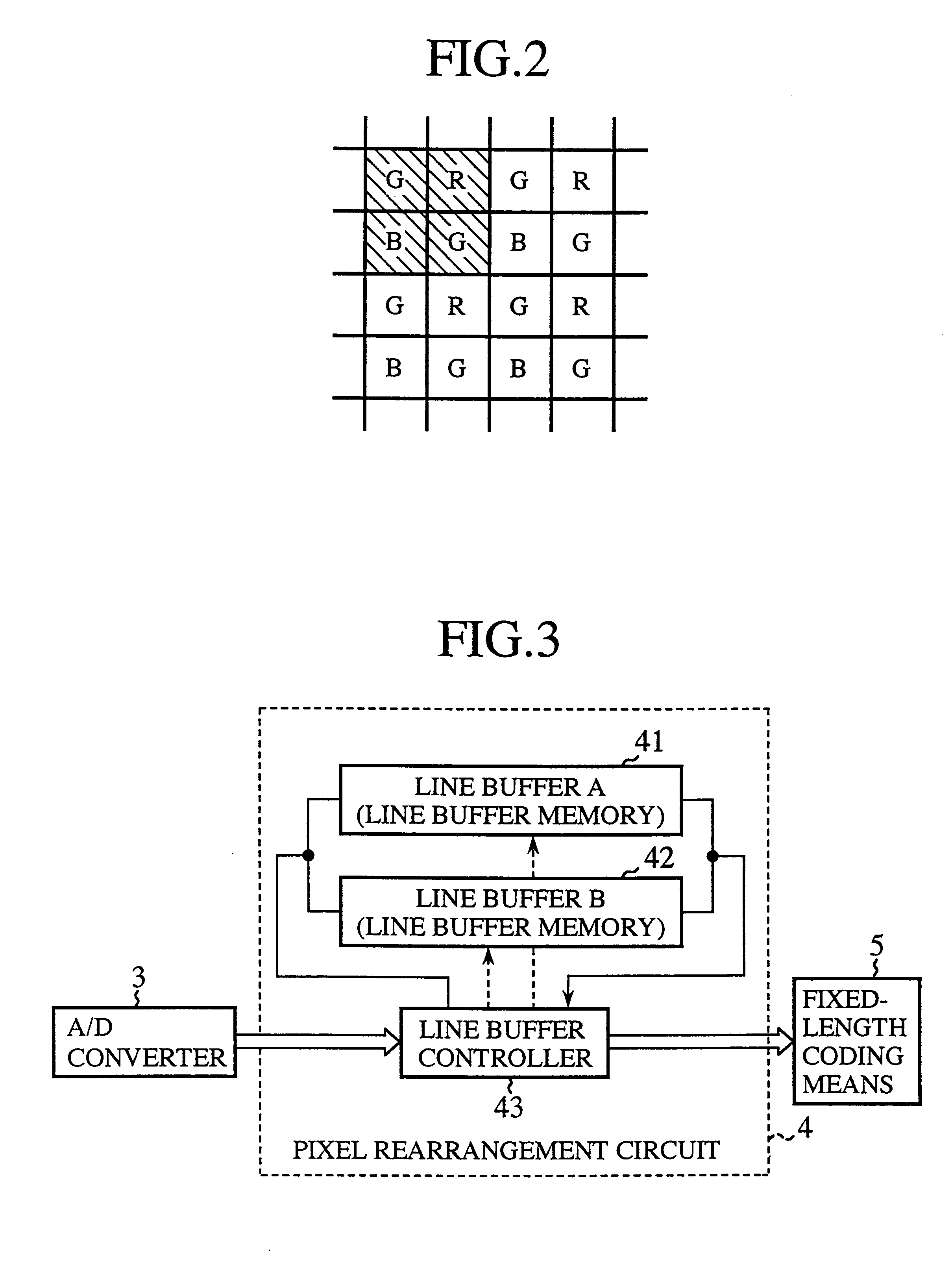
FIG. 1 is a block diagram illustrating a static image pick-up device of the present invention. In FIG. 1, reference numeral 1 denotes a CCD or like single-plate imaging device (an image sensing device) which is provided with color filters of plural colors and from which pixel signals are output on a dot sequential basis; 2 denotes an analog signal processing circuit which performs amplification, filtering and other processing of the output signals from the imaging device 1; 3 denotes an A / D converter for converting analog signals from the analog signal processing circuit 2 into digital signals; 4 denotes a pixel rearrangement circuit (pixel rearrangement means) which rearranges output signals of pixels of R, G and B color components, provided from the A / D converter 3, and outputs them as unit blocks for coding for each color component; 5 denotes a fixed-length coding circuit (fixed-length coding means) which performs fixed-length coding of an FBTC (Fixed Block Truncation Coding) sy...
embodiment 2
FIG. 15 is a diagram showing the results of rearrangement of color image data in the line buffers of the rearrangement circuit of the static image pick-up device according to Embodiment 2 of the present invention. The other parts of this Embodiment 2 are the same as those of Embodiment 1, and hence they will not be described.
In this Embodiment 2, the unit block is formed by 2 by 8 pixels, and the line buffers need only to have four lines each; hence, no large capacity is needed for them. The fixed-length coding / decoding processing is the same as in Embodiment 1 except that the pixel reference position in the unit block (coordinate calculation) differs from the reference position in the case where the unit block is formed from the 4 by 4 matrix of pixels.
embodiment 3
FIG. 16 is a diagram showing the results of rearrangement of color image data in the line buffers of the rearrangement circuit of the static image pick-up device according to Embodiment 3 of the present invention. The other parts of this Embodiment 3 are the same as those of Embodiment 1, and hence they will not be described.
In this Embodiment 3, the unit blocks of the R and B signals are each formed by 2 by 8 pixels, whereas the unit block of the G signal whose quality deterioration is noticeable is formed by 4 by 4 pixels.
According to this Embodiment 3, two lines of coding / decoding are required corresponding to two kinds of unit block sizes (4 by 4 and 2 by 8), but as is the case with Embodiment 2, the line buffers need only to have four lines each; hence, no large capacity is needed for them. Furthermore, since the G signal whose quality deterioration is noticeable is processed as the 4 by 4 unit block, it is possible to obtain a display image of suppressed quality deterioration....
PUM
 Abstract
Description
Claims
Application Information
 - R&D
- Intellectual Property
- Life Sciences
- Materials
- Tech Scout
- Unparalleled Data Quality
- Higher Quality Content
- 60% Fewer Hallucinations
Browse by: Latest US Patents, China's latest patents, Technical Efficacy Thesaurus, Application Domain, Technology Topic, Popular Technical Reports.
© 2025 PatSnap. All rights reserved.Legal|Privacy policy|Modern Slavery Act Transparency Statement|Sitemap|About US| Contact US: help@patsnap.com


