Timber incisor

a technology of incisors and timber, which is applied in the manufacture of wooden sticks, wood compression, profiling/shaping machines, etc. it can solve the problems of time-consuming and expensive replacement of teeth, affecting the quality of wood, and reducing the incidence of broken, bent or lost teeth. , to achieve the effect of reducing the incidence of broken, bent or lost teeth

Inactive Publication Date: 2001-08-21
RITA JOHNSTON & THE ESTATE OF JAMES JOHNSTON
View PDF9 Cites 5 Cited by
  • Summary
  • Abstract
  • Description
  • Claims
  • Application Information

AI Technical Summary

Benefits of technology

An inventory of plate arrays having incisor teeth positioned in a desired pattern can be maintained. When an incising job requires a desired pattern, such as a pattern that might be specified by AREMA, an incisor drum assembly can be made up of plate arrays having a desired configuration to perform the specified incising pattern. Because the incisor teeth of the plate arrays integrally formed with the incisor plate they are less likely to bend or break during use.
It is still another object of this invention to provide an incisor drum that can be easily disassembled and reassembled for maintenance and replacement of plate arrays.
It is still another object of this invention to provide plate arrays for an incising drum that are comprised of plates having incising teeth integrally formed with the plate to maintain the teeth in a fixed and stable position on the drum and reduce the incidence of broken, bent or lost teeth that may result in irregular incising patterns.

Problems solved by technology

Teeth in such drum assemblies are often bent, broken or lost during the incising process.
Drum having bent, broken or lost incising teeth will produce irregular or unwanted incising patterns.
Replacement of these teeth is time consuming and expensive and increases the cost of the incising process.
This presents a disadvantage when tooth rings must be replaced during maintenance of the incisor drum.
The disassembly and re-assembly of the many tooth and spacer rings in the desired configuration increases the time and therefore the cost of the drum maintenance.
Another disadvantage of Toberg is that the fixed angular position of the keyway on the tooth rings limits the amount of adjustment and variation that can be made to the array of teeth on the drum form from such rings.
This in turn limits the adjustments that can be made to points of incising on the timber as it is drawn through an incising machine.

Method used


Image

  • Timber incisor
  • Timber incisor
  • Timber incisor

Examples


Embodiment Construction

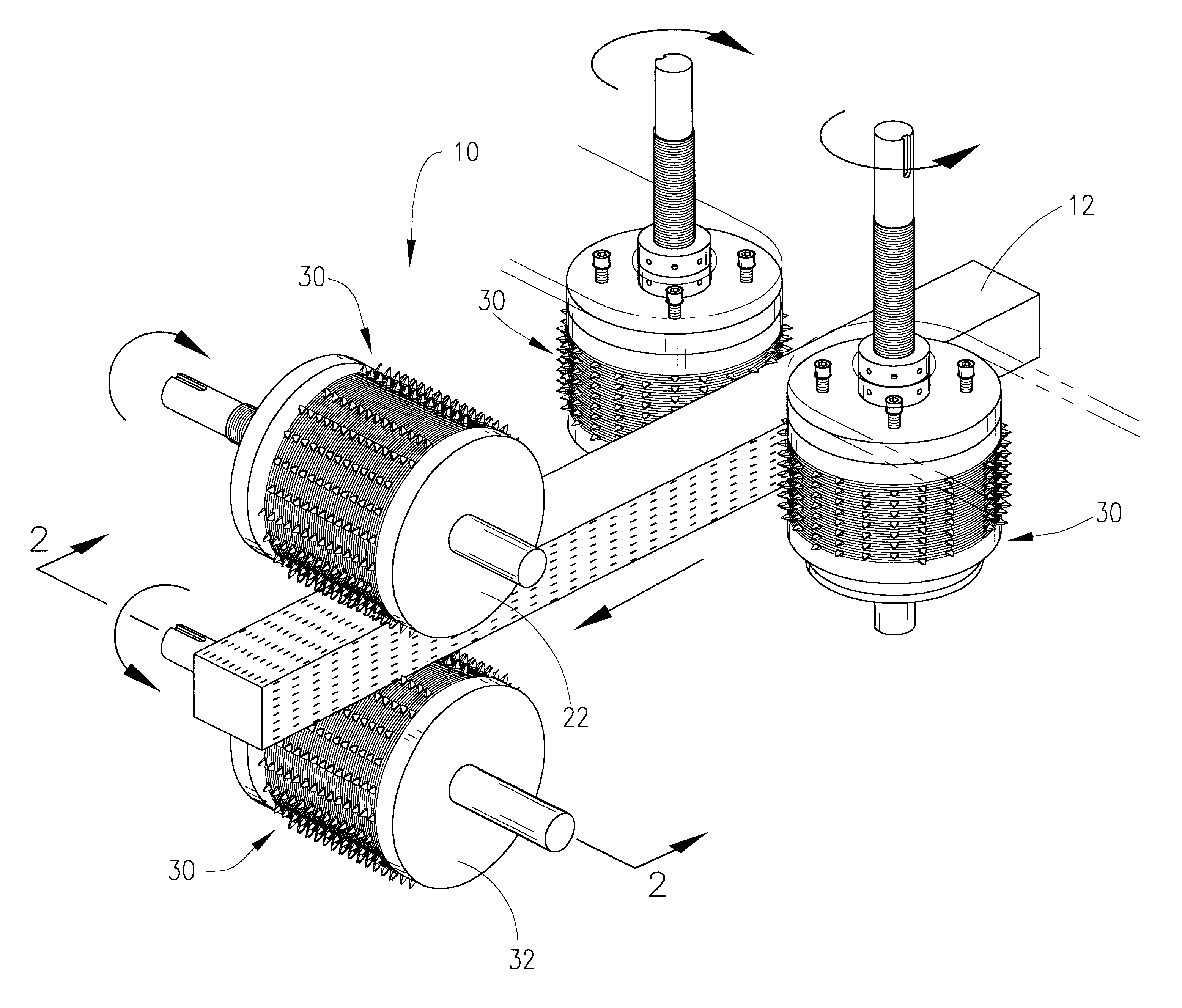
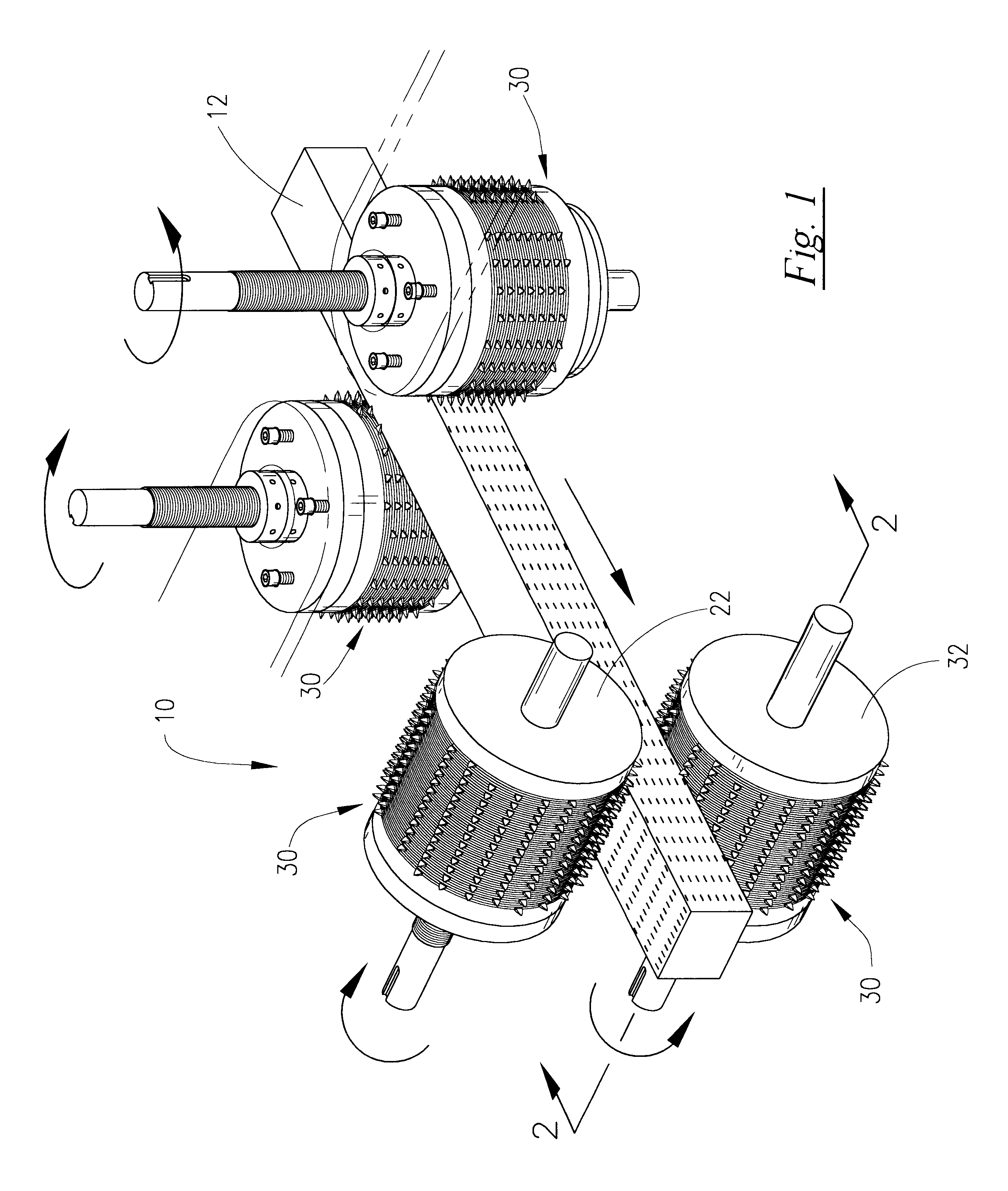
Referring now to the drawings and more particularly to FIG. 1, there is shown a schematic representation of a typical incising drum configuration (10) for incising a rectangular timber tie (12). In the preferred embodiment, incising drum assemblies (30) are mounted within an incising machine for rotating the drum assemblies. Drum assemblies (30) are positioned above and below and on either side of the timber tie (12). When a timber tie (12) is placed between the rotating drum assemblies (30), a desired pattern of perforations or incisions (14) is imparted to the outer surfaces of the timber tie (12).

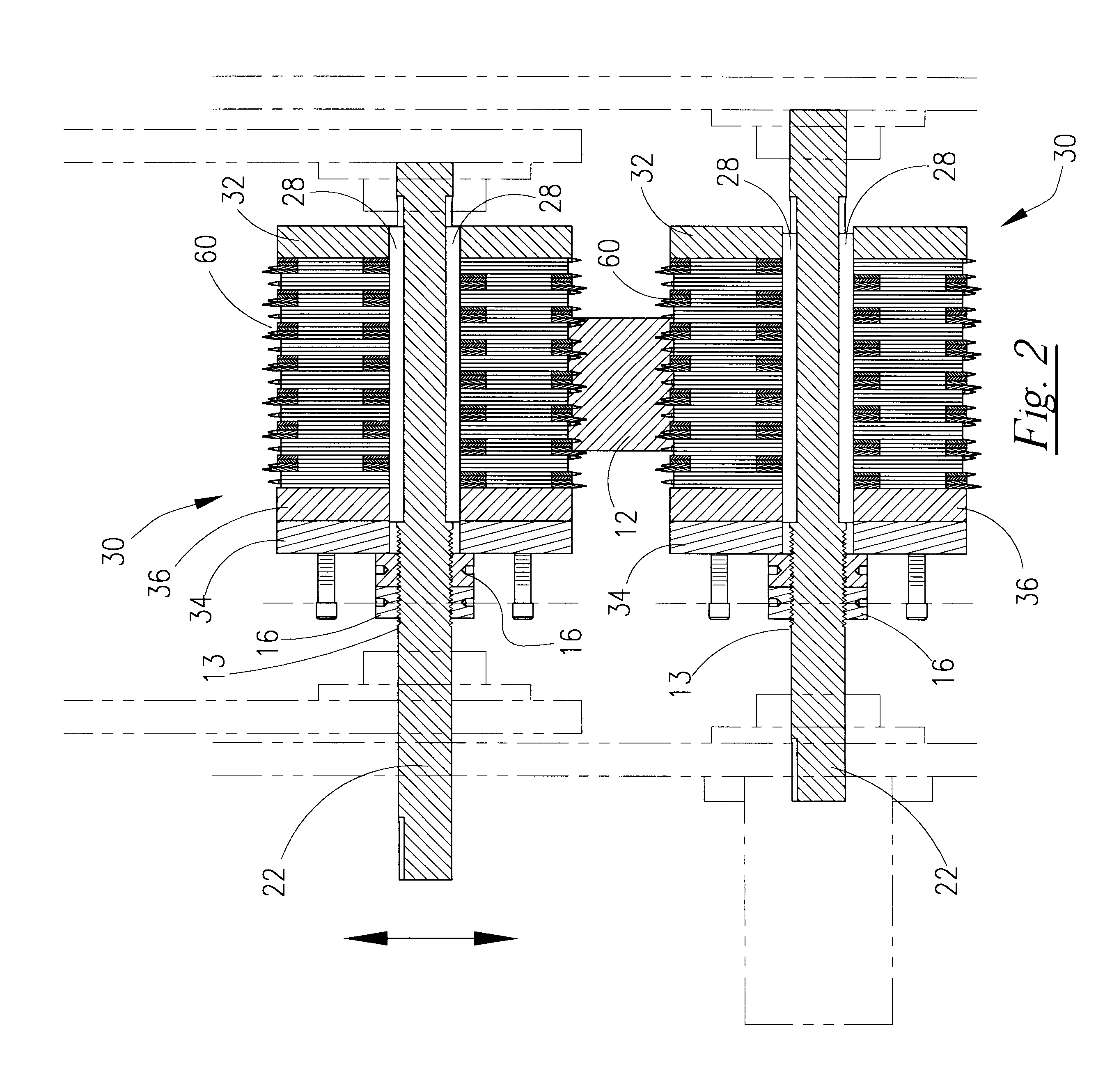
FIG. 2 shows a cross-sectional elevation view of the timber incising configuration of FIG. 1. Incising drum assemblies (30) are positioned above and below timber tie (12) for imparting insising to the upper and lower surfaces of the tie (12). Each drum assembly (30) is comprised of a plurality of incisor plate arrays (60) mounted along a rotatable shaft (22). The plate arrays (60) are po...


PUM


Abstract

In a timber incising machine incorporating a shaft mounted rotating incisor drum, an improved incising drum comprising a shaft configured for rotation by the incising machine; a plurality of circular incisor plates, each of the incisor plates having a plurality of equally spaced incisor teeth extending radially from the radial edge of the circular incisor plates at a desired location. A plurality of incisor plates are stacked in a desired quantity and positioned to place the incisor teeth in a desired pattern and fixed together to form a plate array as a single unit. A plurality of the plate arrays are mounted on the shaft so as to form a rotatable drum having a plurality of radially extending incisor teeth positioned in a desired pattern.

Description

This invention generally relates to the field of incising wooden timbers to enhance the timber curing and treating process. More particularly, it provides an improved incising blade and blade configuration for perforating the surfaces of rectangularly cross-sectioned timber in a desired pattern.BACKGROUND OF INVENTIONWooden timbers such as those to be used for railroad ties are cured and treated to enhance their structural integrity and serviceability. Standards for treating and curing railroad ties have been adopted, an example of such standards being those set forth in the Manual for Railway Engineering provided by AREMA, the American Railway Engineering and Maintenance-of-way Association. AREMA requires that outer surface of railroad ties be perforated or incised during the curing process in order to reduce checking or splitting of the ties. Such incising is to be performed in a specified pattern of perforations.Incisors having driven drums with protruding teeth are often utilize...

Claims


Application Information

Patent Timeline
Patent Type & Authority Patents(United States)
IPC IPC(8): B27G13/00B27M1/00
CPCB27M1/006B27G13/005
Inventor JOHNSTON, JAMES E.JOHNSTON, RITA VIDRINE
Owner RITA JOHNSTON & THE ESTATE OF JAMES JOHNSTON
Why Eureka
Try Eureka