
Imaging-infrared skewed-cone fuze

a fuze and infrared technology, applied in the field of target fuzing, can solve the problems of cov problem, variable-angle right cone, impracticality of vacuum tube and waveguide antennae,

Inactive Publication Date: 2001-08-28
NORTHROP GRUMMAN SYST CORP
View PDF13 Cites 46 Cited by
  • Summary
  • Abstract
  • Description
  • Claims
  • Application Information

AI Technical Summary

Problems solved by technology

Unfortunately, this proved impractical to do with vacuum tubes and waveguide antennae.
(Even variable-angle right cones were found impractical).
And no solutions to the COV problem a crude radar or thermal centroiding beyond were offered with an approximate time delay between target detection and firing to permit COV approach.
At best this means larger time delays to cover all encounters, and larger fuzing errors with incomplete / inaccurate encounter information.
The problems of this approach are expense, fragility, and crude, partial and late imaging as the target sweeps past the skewed-cone, requiring imprecise aim-point selection and millisecond warhead aiming.

Method used


Image

  • Imaging-infrared skewed-cone fuze
  • Imaging-infrared skewed-cone fuze
  • Imaging-infrared skewed-cone fuze

Examples


Embodiment Construction

The elements of the preferred embodiment shown in FIGS. 4 and 5, depending on the application, are (1) One or two 180-degree fisheye lenses imaging forward and optionally rearward hemispheres; (2) One or two 64-element infrared detector arrays and associated optics (three-degree resolution); (3) A digital microprocessor; (4) An aimable warhead; and (5) Ancillary devices including power supplies, cooling and safety and arming units.

Sensor

Passive infrared is the medium of choice because it offers sufficient range and resolution even in adverse weather, against expected powered and / or high-speed aero-heated targets, at minimal aperture, hardware and energy costs. The optimum infrared frequency band(s) depend upon the application. The usual clutter and countermeasure problems of passive IR are eliminated by image processing.

Given a place in the nose of the carrier, the invention may comprise either a single body-fixed 180-degree fisheye lens, or a single side-mounted lens rolled to the ...


PUM


Abstract

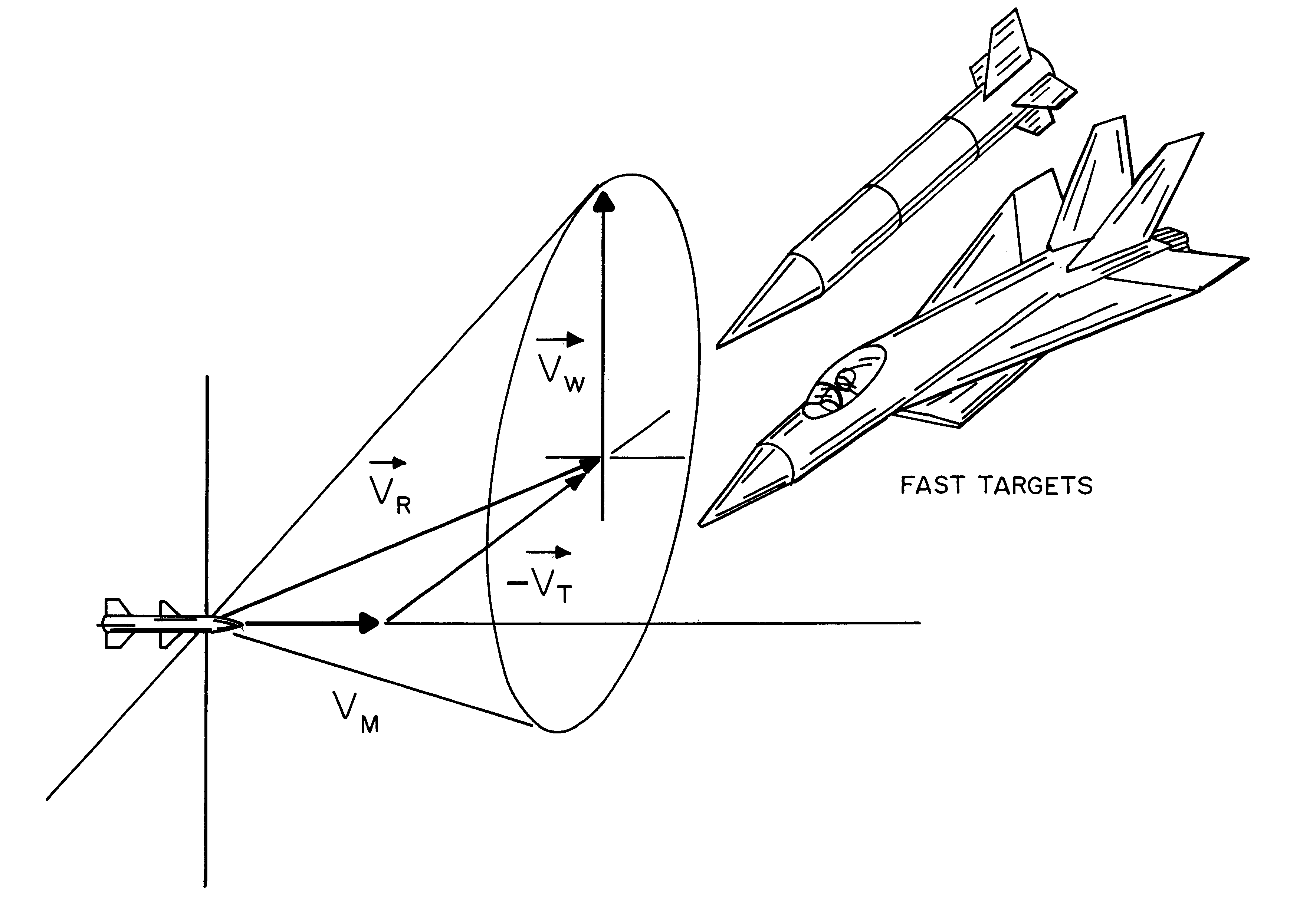
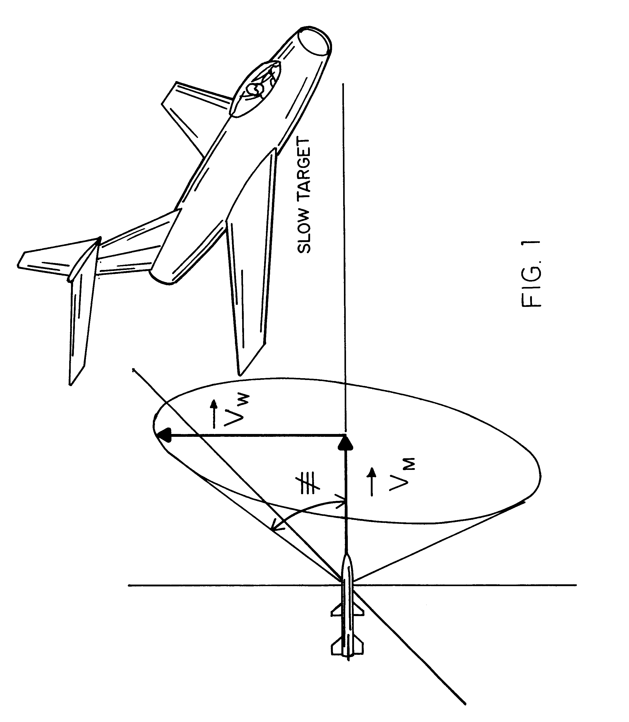
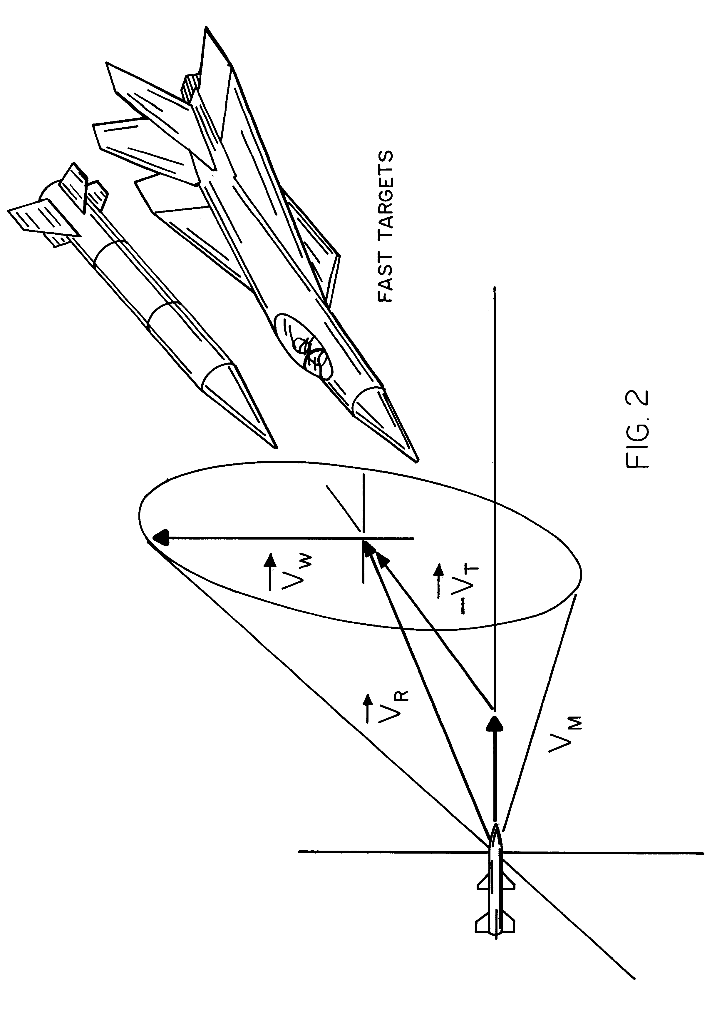
A fuzing system for non-spinning or substantially non-spinning weapons is implemented by means of wide angle optics providing at least forward-hemisphere coverage, an array of infrared detectors and a microprocessor for image and data processing, aim-point selection, directional-warhead aiming and skewed-cone fuzing. The skewed-cone fuzing has a generatrix which is the vector sum of missile velocity, warhead velocity and the negative of target velocity.

Description

1. Field of the InventionThe field of this invention is generally target fuzing and specifically air-target fuzing, although many types of surface targets can be served, too. The invention also relates to the fields of: (1) Air-Targets-Aircraft, Helos, Missiles, RV's and RPV's; (2) WideAngle, Body-Fixed, and Passive Imaging-infrared Sensing and Target Detection Devices; (3) Skewed-Cone Fuzing with Aim-Point Selection and Directional-Warhead aiming; and (4) Non-Spinning or Slowly-Spinning weapons.2. Prior ArtThe first anti-aircraft projectile proximity fuze, a radio-frequency-field motion detector. was developed in 1942. It provided very crude target location, literally proximity, based on signal amplitude, and detonated a nearly-omni-directional blast-fragment warhead.Near the end of World War II, evolving radar and anti-aircraft missile technology combined to produce the fixed-angle microwave fuze. Centimeter-wavelength antennae about the missile periphery created a forward-looking...

Claims


Application Information

Patent Timeline
Patent Type & Authority Patents(United States)
IPC IPC(8): F42C13/02F42C13/00F42B12/02F42B12/24
CPCF42C13/02F42B12/24
Inventor RINGER, HAYDEN N.SHREKENHAMER, ABRAHAM
Owner NORTHROP GRUMMAN SYST CORP
Learn More