Non-planar Q-switched ring laser system

a laser system and ring technology, applied in semiconductor lasers, laser details, optical resonator shape and construction, etc., can solve the problems of reducing the efficiency of lasers, increasing the complexity and expense of lasers, and reducing the alignment sensitivity of lasers such as used in laser radar and industrial applications. , to achieve the effect of simple monolithic resonator structure, reduced alignment sensitivity, and high power

Inactive Publication Date: 2001-08-28
RAYTHEON CO
View PDF8 Cites 13 Cited by
  • Summary
  • Abstract
  • Description
  • Claims
  • Application Information

AI Technical Summary

Benefits of technology

It is a further object of this invention to provide such a non-planar passively Q-switched ring laser system which is high power and optically self-aligning.
It is a further object of this invention to provide such a non-planar passively Q-switched ring laser system with greatly reduced alignment sensitivity.
It is a further object of this invention to provide such a non-planar passively Q-switched ring laser system with simple monolithic resonator structure.
It is a further object of this invention to provide such a non-planar passively Q-switched ring laser system which is reliable, robust, low maintenance and high performance.
It is a further object of this invention to provide such a non-planar passively Q-switched ring laser system which tolerates relaxed manufacturing and alignment accuracy.
The invention results from the realization that a reliable, robust, high power laser system with reduced alignment sensitivity can be effected using a Q-switch to increase the power and utilizing the inherent self-aligning properties of a non-planar ring laser configuration to reduce susceptibility to misalignment while avoiding the complexity of an active Q-switch by using a passive Q-switch.

Problems solved by technology

Pulsed lasers such as used in laser radar and industrial applications are limited in output pulse energy by the risk of damage to the internal optics.
However, as the mirror radius is made longer the resonator becomes more susceptible to misalignment: the larger the mirror radius the greater is the shift of the optical axis for a given tilt misalignment of the mirrors or other optical elements of the resonator.
Power output can be enhanced using Q-switching but this adds significant complexity and expense to the laser.

Method used


Image

  • Non-planar Q-switched ring laser system
  • Non-planar Q-switched ring laser system
  • Non-planar Q-switched ring laser system

Examples


Embodiment Construction

Other objects, features and advantages will occur to those skilled in the art from the following description of a preferred embodiment and the accompanying drawings, in which:

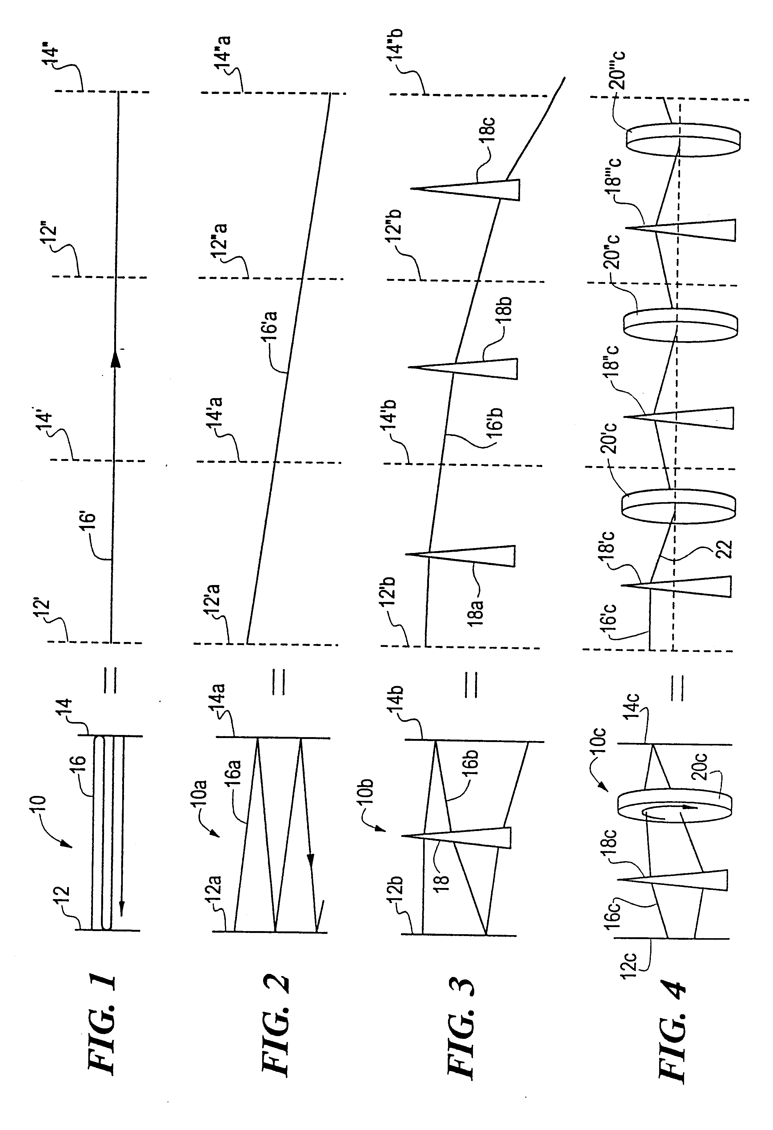
FIG. 1 is a schematic view of a laser beam reflecting back and forth along the optic axis of a resonant cavity and its equivalent in expanded or unfolded form;

FIG. 2 is a view similar to FIG. 1 where the laser beam is at a slight angle to the optic axis;

FIG. 3 is a view similar to FIG. 1 showing rapidly increasing misalignment of the laser beam due to misalignment of optical components as modeled by an intracavity small-angle prism;

FIG. 4 is a view similar to FIG. 1 illustrating the manner in which rotation effected by non-planar ring laser geometry can reduce misalignment of the laser beam;

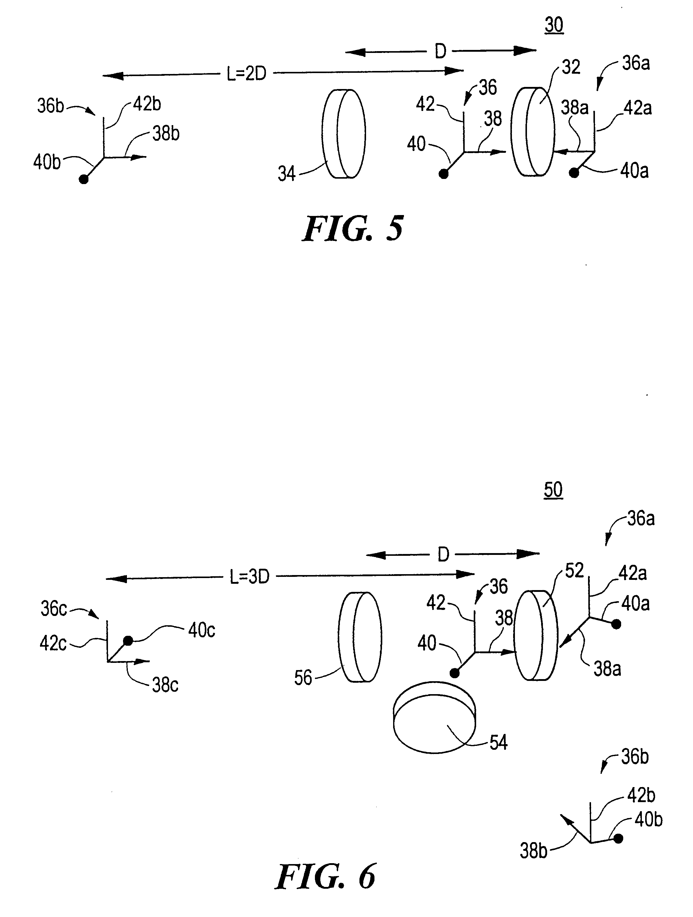
FIG. 5 is a simplified ray diagram showing the effect of reflections in a two-mirror resonator;

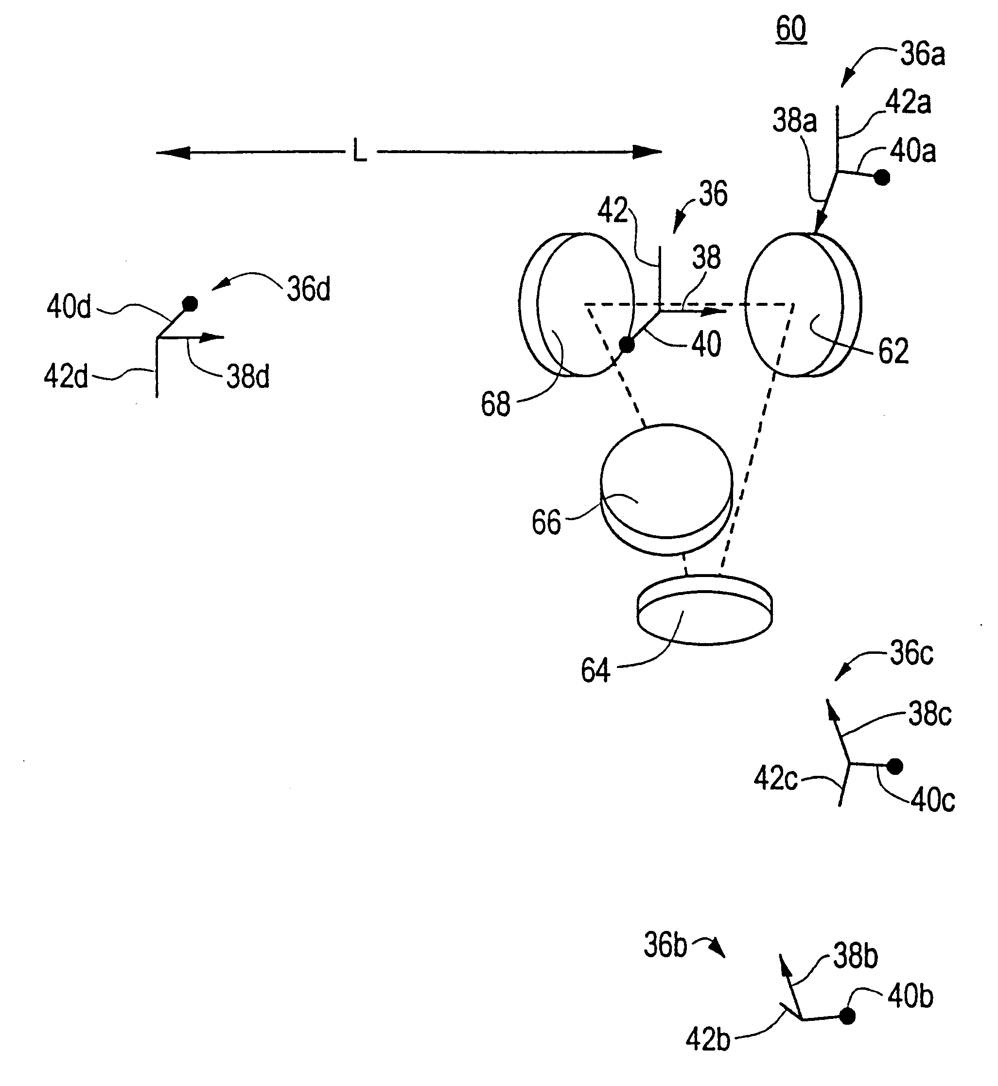
FIG. 6 is a view similar to FIG. 5 for a three-mirror resonator;

FIG. 7 is a view similar to FIG. 5 for a four-mirror non-planar r...


PUM


Abstract

A non-planar Q-switched ring laser system including a ring laser having a gain medium and a closed optical path lying in at least two distinct planes, and a Q-switch in the closed optical path for automatically varying the loss in the closed optical path.

Description

This invention relates to a non-planar, Q-switched ring laser system, and more particularly to a high power, optically self aligning, non-planar Q-switched ring laser system.BACKGROUND OF INVENTIONPulsed lasers such as used in laser radar and industrial applications are limited in output pulse energy by the risk of damage to the internal optics. The output energy can be increased by increasing the mode volume by increasing the radius of curvature of the resonator mirrors. However, as the mirror radius is made longer the resonator becomes more susceptible to misalignment: the larger the mirror radius the greater is the shift of the optical axis for a given tilt misalignment of the mirrors or other optical elements of the resonator. Non-planar ring lasers promote enhanced optic axis stability but the light circulates within a closed path in two distinct directions, e.g., clockwise and counterclockwise, so that the output of such lasers is emitted in two beams which cannot be efficient...

Claims


Application Information

Patent Timeline
Patent Type & Authority Patents(United States)
IPC IPC(8): H01S3/081H01S3/083H01S3/11
CPCH01S3/0606H01S3/0612H01S3/0627H01S3/083H01S3/025H01S3/0405H01S3/1643H01S3/0941H01S3/1066H01S3/113H01S3/1611H01S3/0815
Inventor SMITH, IRL W.SHARP, RICHARD C.
Owner RAYTHEON CO
Why Eureka
Try Eureka