Tufting machine with needle bar motor

a tufting machine and motor technology, applied in the field of tufting machines, can solve the problems of limiting the speed capability of the tufting machine, losing any movement in the coupling mechanism between the servo and the sliding needle bar, and many more complex mechanisms for exerting control over the yarn delivery

Inactive Publication Date: 2001-09-04
SOC DINVESTMENT MOSELLE SA
View PDF4 Cites 32 Cited by
  • Summary
  • Abstract
  • Description
  • Claims
  • Application Information

AI Technical Summary

Problems solved by technology

There are many more complex mechanisms for exerting control over the yarn delivery.
This results in patches of different colors but has a number of disadvantages in the wastage of yarn which cannot be seen and in the straight line arrangement of the colored yarn.
These mechanisms provide the necessary motional requirements from a functional view but also limit the speed capability of the tufting machine.
This limitation may arise due to the speed...

Method used


Image

  • Tufting machine with needle bar motor
  • Tufting machine with needle bar motor
  • Tufting machine with needle bar motor

Examples


Embodiment Construction

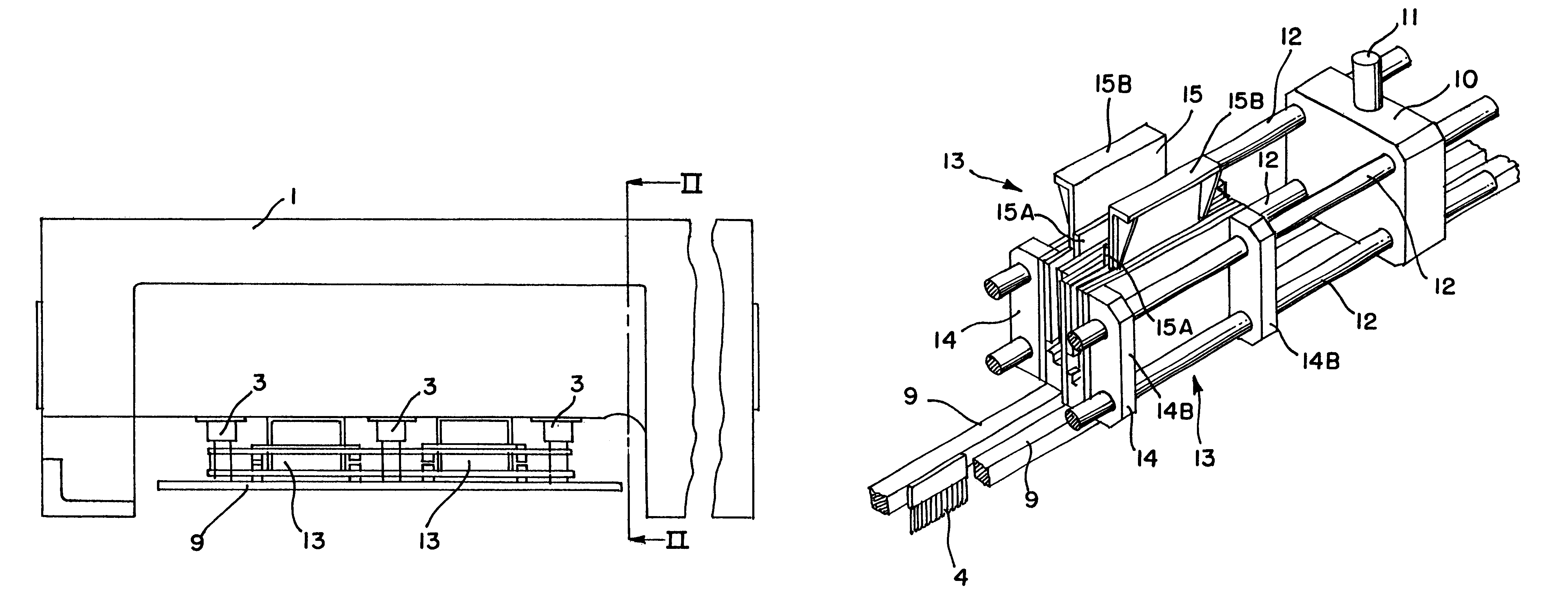
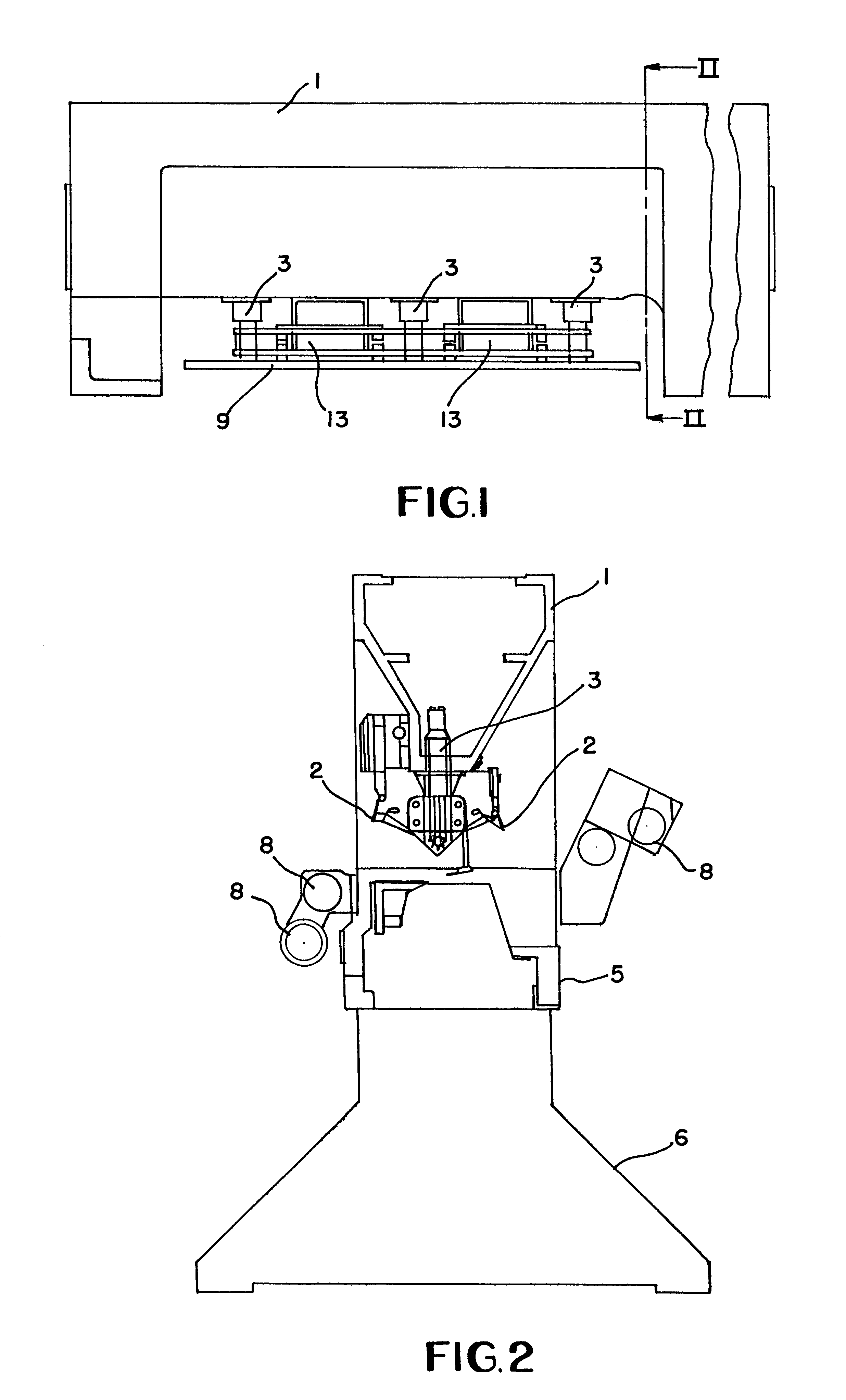
In most respects, the machine is a conventional tufting machine, so that a detailed description of the tufting operation will not be included here. The machine has a top housing 1 housing the yarn feed mechanism 2, and three reciprocating pistons 3 for reciprocating needles 4. A bottom housing 5 is mounted on legs 6 (neither of which are shown in FIG. 1) as is the bed plate 7 and is provided with a series of rollers 8 for feeding the backing medium through the machine. As the backing medium is fed through the machine, the needles 4 are vertically reciprocated by the reciprocating pistons 3 and cooperate with a plurality of hooks or loopers beneath the backing material to produce a tufted carpet in the conventional manner as is well known in the art.

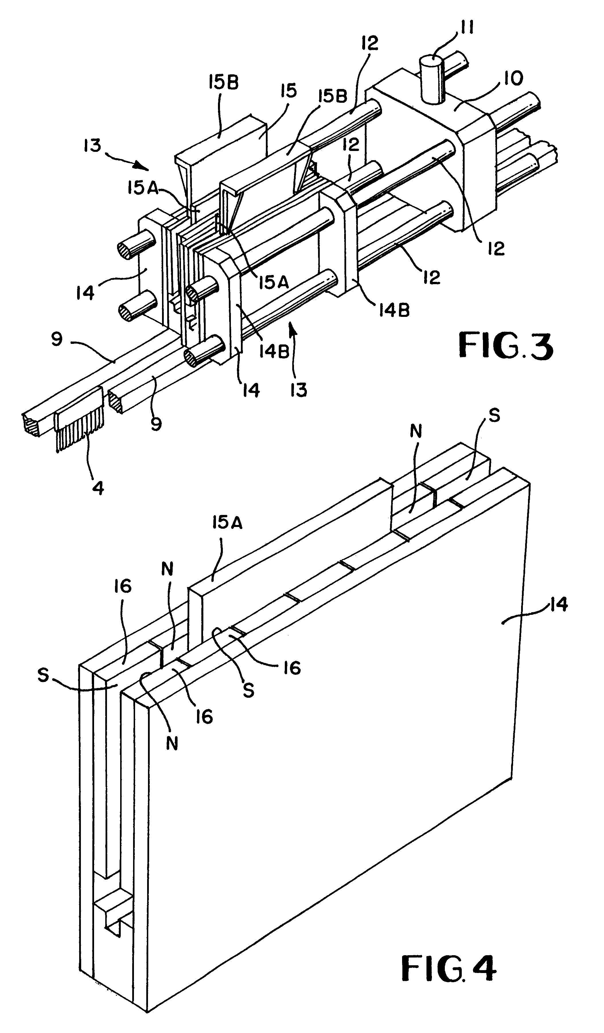
The apparatus shown in FIGS. 3 and 5 comprises a pair of needle bars 9, each of which have needles 4 connected along their length. Three plates 10 are reciprocally vertically movable by means of a respective push rod 11 driven by a respec...


PUM


Abstract

A tufting machine has a reciprocating needle bar which may be shifted laterally by a drive which includes at least one linear motor. Each linear motor has two major elements which may be coupled together electromagnetically. One of the elements is connected to a fixed portion of the tufting machine and another of the elements is connected to the needle bar. When electrical power is supplied to the motor, the element connected to the needle bar moves relatively to the other thereby moving the needle bar.

Description

1. Field of the InventionThe present invention relates to a tufting machine used for carpet manufacture.2. Description of the Related ArtTufting machines are distinguished over other carpet making methods in that loops of yarn which constitute the pile of the carpet are inserted in a backing medium or cloth, which may be fibrous or woven according to the carpet application. The loops are held in place by the retentive pressure of the backing cloth having been expanded locally through the insertion of the yarn. A subsequent operation covers the rear face of the yarn and backing cloth with a retaining adhesive. The adhesive also holds a further layer of backing material, usually hessian.The yarn is inserted into the backing material by a multiplicity of needles which perform a reciprocating motion. The needles have eyes at the lower extremities through which yarn is both fed and captured. Generally, the needles are connected to one or more transverse bars known as needle bars so that ...

Claims


Application Information

Patent Timeline
IPC IPC(8): D05C15/20D05C15/30D05C15/00
CPCD05C15/30D05C15/20
Inventor PRATT, ANTHONY R.
Owner SOC DINVESTMENT MOSELLE SA
Why Eureka
Try Eureka