Fuel-air mixture apparatus

a mixture apparatus and fuel technology, applied in the field of fuelair mixture apparatus, can solve the problems of limited fuel and air mixture in the prior device, unburned and/or incompletely burned fuel in the exhaust of the engine, and limited mixing effect of fuel and air

Inactive Publication Date: 2001-09-04
OMARSSON KRISTJAN BJORN
View PDF9 Cites 28 Cited by
  • Summary
  • Abstract
  • Description
  • Claims
  • Application Information

AI Technical Summary

Benefits of technology

The object of the present invention is to provide a fuel-air mixture apparatus which causes low quantities of unburned and incompletely burnt fuel to be present in the exhaust.

Problems solved by technology

Generally, the prior devices rely on a single stage of mixture of fuel and air and are limited as regards the droplet size and total vaporisation of the fuel in the air which they induce.
Inadequate vaporisation and too large a droplet size result in unburned and / or incompletely burnt fuel being present in the exhaust from the engine.

Method used


Image

  • Fuel-air mixture apparatus
  • Fuel-air mixture apparatus
  • Fuel-air mixture apparatus

Examples


second embodiment

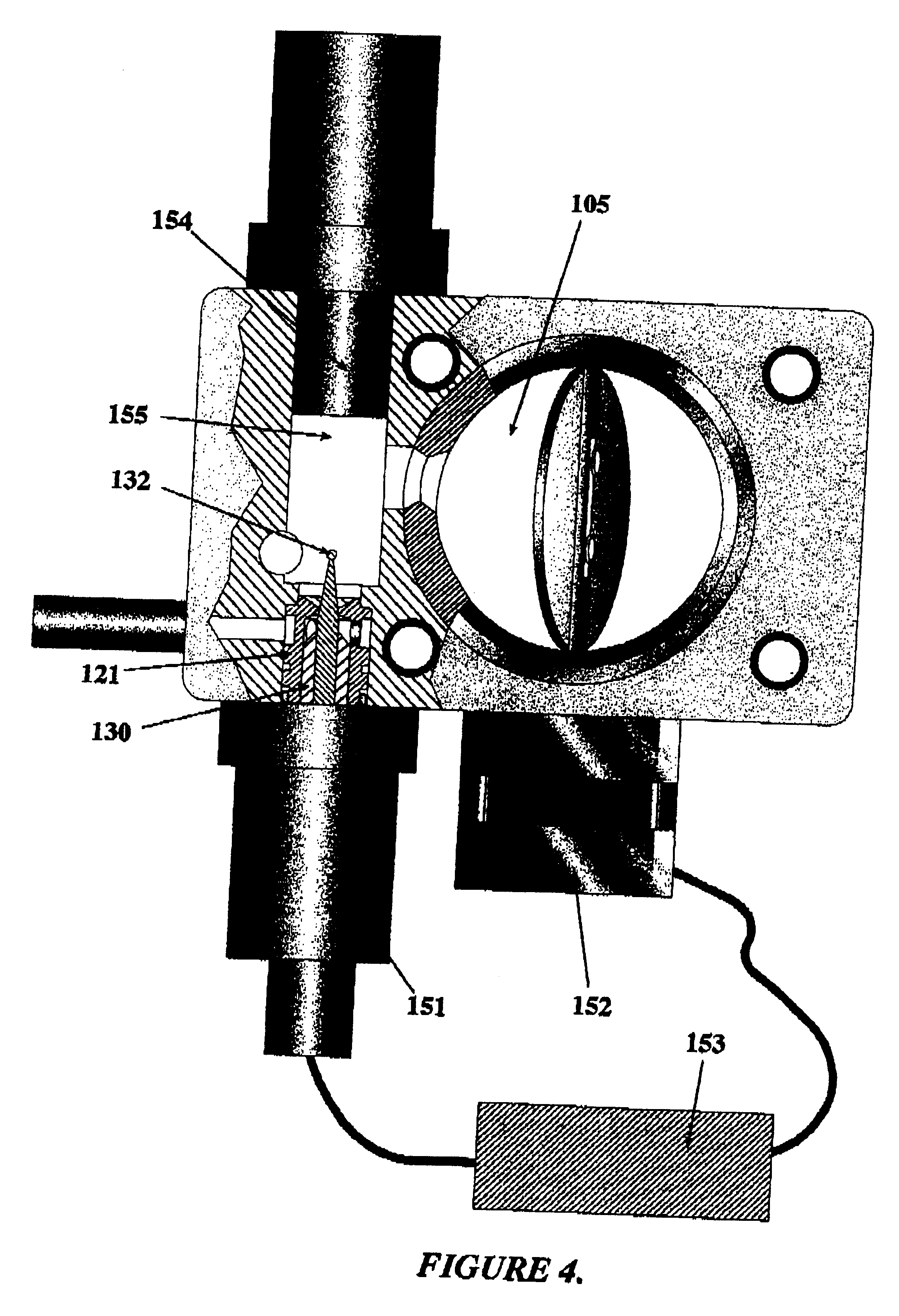
Turning now to FIG. 4, a second embodiment is shown in which the nozzle device 121 is arranged tangentially to the primary air passage 105 arid is of simpler construction, whereby its plug 130 is driven by a threaded shaft output (not shown) from a stepper motor 151 or a linearly controllable, electromagnetic actuator under control from an engine management computer 153, whose programming will be within the domain of the man skilled in the art and will not therefore be described. The computer 153 also controls a second stepper motor 152 connected to the throttle for controlling its position. In addition to the computer control of the needle 132, this embodiment includes an ultrasonic transducer 154 against the face 155 of which the fuel from the needle is introduced. This has the effect of disintegrating the fuel droplets for their vaporisation in the swirling secondary air flow In other respects, this embodiment is similar to the embodiment of FIG. 1.

Variant of the Second Embodimen...

third embodiment

Turning on to FIG. 7, the third embodiment there shown differs from the first and second embodiments in not having a chamber in its secondary air passage 213. Rather its nozzle device 221 incorporates a nose 261 mounted with the device in the bore 218 in the body 202. Tile nose has a lateral inlet 262 for the secondary air flow which impinges on a tip 263 of the needle sleeve 222 and is accelerated as it flows through a tapered outlet 264 of the nose. This outlet has a further taper 265 back-to-back with tile taper 264, forming a constriction 266, causing the secondary air to be turbulent on leaving the nose. The constriction is arranged to be the outlet of the secondary air passage. The fuel introduction orifice, between the nozzle 221 and the needle 232 is close to the constriction, with the needle actually extending into the constriction. The arrangement induces fine fuel droplet formation and vaporisation of the fuel in the secondary air as it mixes with the primary air flow.

It ...


PUM

PropertyMeasurementUnit
diameteraaaaaaaaaa
pressureaaaaaaaaaa
air flow speedaaaaaaaaaa

Abstract

An improved fuel air mixture apparatus which enhances the degree of mixing of fuel with air. The fuel-air mixture device includes a primary air passage having an inlet, an adjustable throttle and an outlet; a secondary air passage having an inlet and an outlet to the primary air passage between its adjustable throttle and its outlet; a nozzle having an orifice opening into the secondary air passage for introducing a flow of fuel therein; a needle arranged co-axially of the nozzle with its small diameter at least normally extending from the orifice into the secondary air passage, the needle being axially moveable to provide variability of the orifice and control of the fuel flow; a control device for directly linking or controlling the position of the needle to the position of the adjustable throttle in the primary air passage for adjustment of the orifice of the nozzle. The arrangement is such that the fuel flow from the nozzle is matched to the position of the adjustable throttle and the fuel flowing from the orifice towards the small diameter end of the needle mixes with air flowing through the secondary passage prior to mixing with the air flowing through the primary air passage.

Description

The present invention relates to a fuel-air mixture apparatus, particularly for an internal combustion engine.Fuel-air mixture apparatuses of the type where fuel is mixed with air prior to induction into the cylinder(s) of an engine generally rely on a pressure reduction at a throttle in the device to draw fuel into the device, in which case the device is known as a carburettor, or rely on fuel injection into the air as it passes through the device.Generally, the prior devices rely on a single stage of mixture of fuel and air and are limited as regards the droplet size and total vaporisation of the fuel in the air which they induce. Inadequate vaporisation and too large a droplet size result in unburned and / or incompletely burnt fuel being present in the exhaust from the engine.THE INVENTIONThe object of the present invention is to provide a fuel-air mixture apparatus which causes low quantities of unburned and incompletely burnt fuel to be present in the exhaust.The fuel-air mixtur...

Claims


Application Information

Patent Timeline
Patent Type & Authority Patents(United States)
IPC IPC(8): F02M3/00F02M7/22F02M7/00F02M3/10F02B29/06F02M19/04F02M23/12F02M27/08F02M69/04
CPCF02M3/10F02M7/22Y10S261/01Y10S261/48Y10S261/38
Inventor OMARSSON, KRISTJAN BJORN
Owner OMARSSON KRISTJAN BJORN
Why Eureka
Try Eureka