Metal-air cathode can, and electrochemical cell made therewith

a cathode can and metal-air technology, which is applied in the direction of cell components, cell components, jackets/cases materials, etc., can solve the problems that the relationship between the opening and the thickness of the bottom of the can may become less relevant, and achieve the effect of reducing the weight loss due to moisture evaporation and maintaining the electrical performance characteristics of the cell

Inactive Publication Date: 2001-09-04
ROVCAL +1
View PDF57 Cites 10 Cited by
  • Summary
  • Abstract
  • Description
  • Claims
  • Application Information

AI Technical Summary

Benefits of technology

In the second step, the metal around the port is worked, such as by peening, causing the metal to flow, thereby to reduce the size of the hole. In preferred embodiments, the metal about the hole is restrained during the peening step, such that the peening directs the metal preferentially inwardly toward the hole. Using the restrained peening process, the size of the hole can be reduced to make any size port greater than complete closure of the hole. The restrained peening step can even be used to completely reclose the so formed hole. Thus, the restrained peening step is effective to completely close the so-formed hole / port, or to provide any size port from the minimum size port that can be detected, up to the size of the hole initially created in the conventional hole-forming step.
In addition to serving as a passageway for conduct of oxygen to the reaction surface, air reservoir 52, with cooperation of air diffusion layer 21, serves as an air accumulation chamber, holding enough oxygen "fuel" to provide for a temporary increase in the current-producing capability of the cell, sometimes also referred to as the "pulse" capability of the cell. Air reservoir 52 also serves as a damping chamber to damp, namely to reduce, any variation in the rate at which oxygen enters the air reservoir.
Prior to this invention, there was no known method for predictably affecting the balance of these concurrent events to thereby maintain or improve performance of the cell while reducing transport of water vapor into or out of the cell through the air ports.
To the extent the open cross-sectional area of the ports is large, relative humidity equilibrium between ambient air and the air reservoir is reached rather quickly, such that 95% of an initial relative humidity differential may be eliminated in a few days, whereby the relative humidity inside the cell approaches ambient relative humidity; never the reverse. To the extent the cross-sectional area of air ports 34 is less, it takes longer to reach relative humidity equilibrium. The longer time for reaching relative humidity equilibrium, whereby the relative humidity inside the cell is maintained generally closer to ideal conditions for a relatively longer period of time, results in improved cell performance over that longer period of time.
By studying phenomena related to gaseous transport of oxygen and air, gaseous transport of moisture vapor, and the properties of corresponding metal-air cells, the inventors herein have discovered that, for a given cell size and structure, the amount of moisture lost from the cell, relative to the amount of electricity produced, can be reduced by using a larger number of spaced, relatively smaller holes in place of the conventionally used larger holes. In addition, the inventors herein have surprisingly discovered that, considering known electrical performance characteristics for a given cell, and considering a conventional port configuration, cell electrical performance characteristics can be maintained while the weight loss due to moisture evaporation is reduced, by increasing the number of ports while reducing the composite sum of the area represented by all of the respective ports.

Problems solved by technology

However, as can forming technology improves, to enable making the can bottom thinner, the above stated relationship between size of the opening and thickness of the bottom of the can may become less relevant.

Method used


Image

  • Metal-air cathode can, and electrochemical cell made therewith
  • Metal-air cathode can, and electrochemical cell made therewith
  • Metal-air cathode can, and electrochemical cell made therewith

Examples


examples 2 , 12

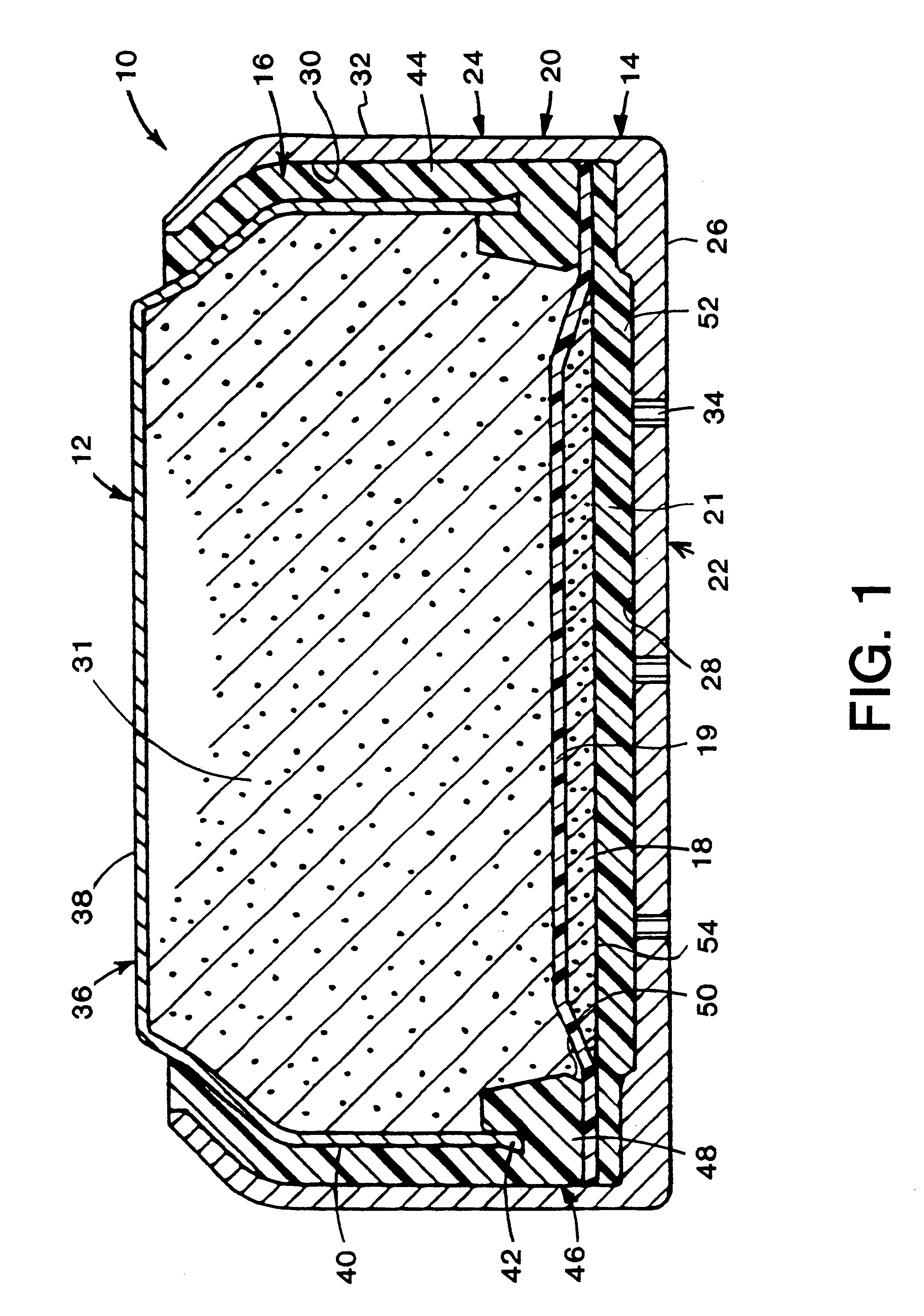
Examples 2, 12, and 24 suggest that the preferred port size depends in part on the absolute size of the imaginary closed area 56 represented by the intersection of the plume 58 with the reaction surface 54. Assuming each port supports an equal proportion of the reaction surface (Active Area), each port in Example 2 supports 0.701 / 6=117 mm.sup.2 of the reaction surface while each port in Examples 12 and 24 supports 72 mm.sup.2 and 96 mm.sup.2 respectively. Thus, in general, the smaller the area of the reaction surface to be supported by each port, the smaller the port size can be.

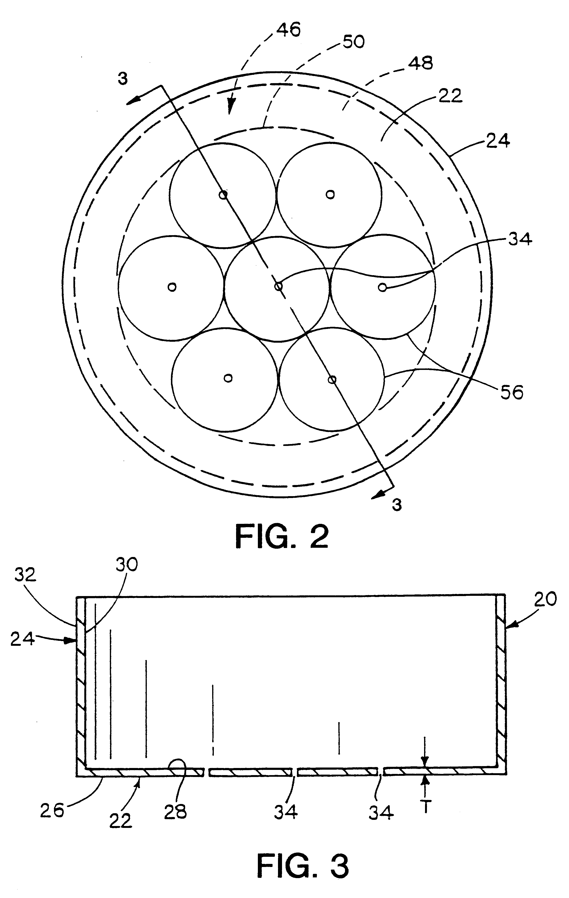
Following the empirical data of e.g. FIG. 6 to its logical conclusion, the ideal port configuration comprises an infinitely large number of ports evenly distributed on the bottom 22, adjacent reaction surface 54, each port being infinitesimally small in size.

However, from a practical standpoint, the actual number of ports will generally be finite, and will be governed at least in part by the incremental incr...


PUM

PropertyMeasurementUnit
diameteraaaaaaaaaa
effective diameteraaaaaaaaaa

Abstract

This invention pertains to metal-air electrochemical cells wherein one or more air entry ports is located in the bottom of the cathode can, to provide for entry of oxygen-rich air into the cathode can, where the oxygen participates in the electrochemical reaction whereby the cell produces electrical energy. In this invention, extremely small air ports are provided, along with methods of reliably fabricating such small air ports, where a tool impression extends around the port. Generally, the use of an increased number of small air ports distributed over the bottom of the cathode can, opposite the reaction surface of the cathode assembly, wherein the overall open area of the ports is not increased, results in less moisture traversing the air ports, into or out of the cell. Accordingly, moisture loss, or gain, as a function of electrical energy produced, is thereby reduced.

Description

This invention relates to alkaline electrochemical cells having metallic anodes and air cathodes, commonly known as metal-air cells, and especially to zinc-air cells. More particularly, this invention relates to the structure of the cathode can, namely to the sizes of air ports used on the bottom of the cathode can and methods for fabricating the cathode can to make air ports as herein disclosed. The air ports of the invention have specifically limited open area to provide ingress of air containing cathodic oxygen, while restricting water vapor movement.The growth in use of portable electrically-powered devices has increased the demand for small power sources, and especially metal-air electrochemical cells. Such small cells are usually disc-like or pellet-like in appearance, and may be similar in size to garment buttons, although they can be either smaller or larger. Typical such cells generally have diameters ranging from less than 0.25 inch (6 millimeters) up to about 1.0 inch (25...

Claims


Application Information

Patent Timeline
Patent Type & Authority Patents(United States)
IPC IPC(8): H01M4/42H01M4/24H01M12/06H01M2/02H01M4/62H01M12/00H01M50/119H01M50/133
CPCH01M2/0222H01M2/0257H01M2/027H01M2/0272H01M2/0275H01M4/42H01M4/62H01M12/06H01M4/244Y02E60/124H01M2300/0085Y02E60/10H01M50/109H01M50/545H01M50/1243H01M50/133H01M50/119
Inventor ADEY, ROBERTDOPP, ROBERT BRIANOLTMAN, JOHN EDWARD
Owner ROVCAL
Why Eureka
Try Eureka