Valve assembly for controlling fluid ingress and egress from a transportable container which stores and distributes liquid under pressure

a technology of valve assembly and container, which is applied in the direction of transportation and packaging, machines/engines, liquid transferring devices, etc., can solve the problems of valve components being out of the container opening at high speed, substantial risk to personnel and/or surroundings, and not solving other problems, so as to enhance the self-threading nature of the retainer assembly

Inactive Publication Date: 2001-09-11
VENT MATIC +1
View PDF5 Cites 41 Cited by
  • Summary
  • Abstract
  • Description
  • Claims
  • Application Information

AI Technical Summary

Benefits of technology

The retainer assembly preferably further comprises first and second radially tapered, vertically extending centering skids that are spaced circumferentially from one another and from the protrusion. In order to permit the valve cup to rock about the centering skids to wedge the protrusion against the stub, both of the centering skids taper radially inwar

Problems solved by technology

Residual gas pressure in the container can force the valve components out of the container opening at high velocities with substantial risk to personnel and/or surroundings.
The valve assembly disclosed in the Riis patent, though solving at least one of the problems exhibited by most valve assemblies, does not solve other problems associated with conventional valve assemblies.
For instance, it cannot relieve excessive gas pressures within the container which may be generated when the container is subjected to external forces such as excessive shaking or other mechanical agitation or fire or other thermal agitation.
Hence, traditional valve assemblies cannot prevent gas pressures within the container from reaching or even exceeding explosive levels in the presence of external agitation forces.
Even if these external forces are less severe such that gas pressures within the container do not reach explosive levels, the higher-than desi

Method used


Image

  • Valve assembly for controlling fluid ingress and egress from a transportable container which stores and distributes liquid under pressure
  • Valve assembly for controlling fluid ingress and egress from a transportable container which stores and distributes liquid under pressure
  • Valve assembly for controlling fluid ingress and egress from a transportable container which stores and distributes liquid under pressure

Examples


first embodiment

2. Description of First Embodiment

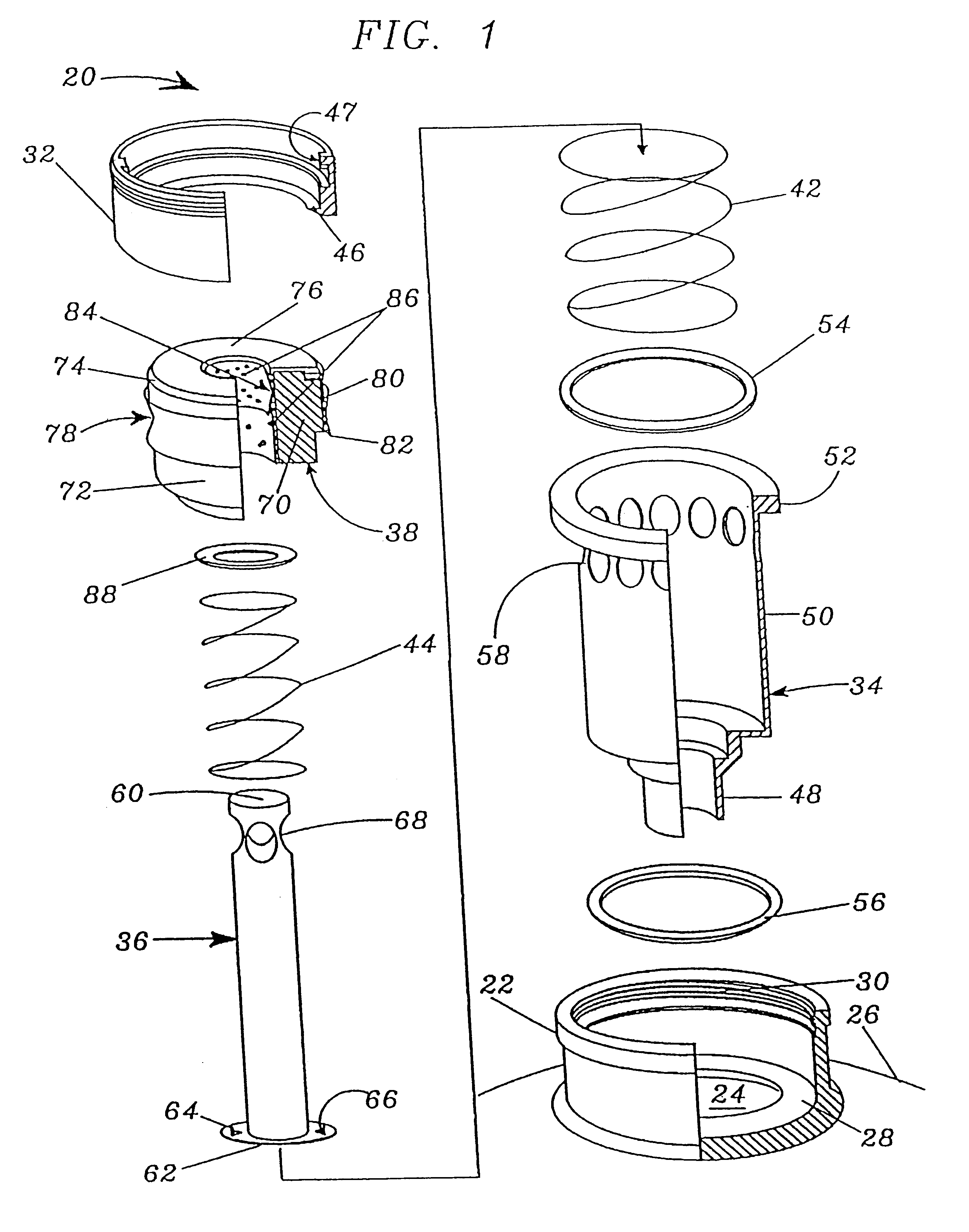
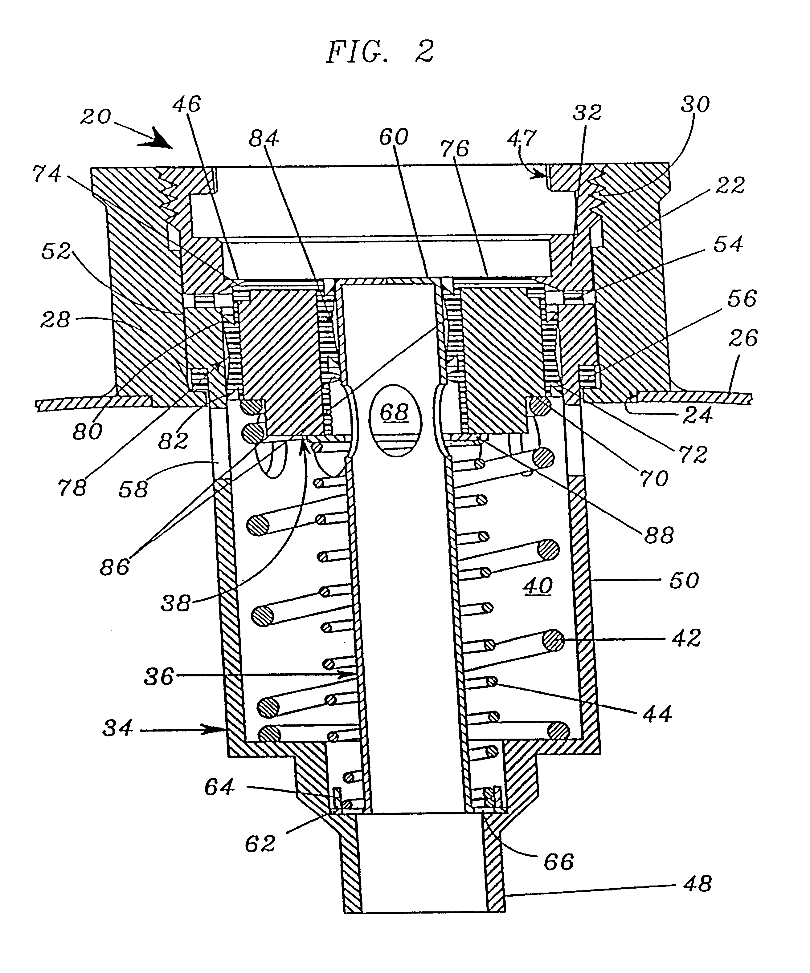
Turning now to the drawings and initially to FIGS. 1-4 in particular, the inventive valve assembly 20 is designed for connection to a standard stub 22 surrounding an aperture 24 in a container 26. Container 26 may comprise a barrel or any other transportable or stationary structure for storing beverages or other liquids and for dispensing the stored liquids under gas pressure. The stub 22 coaxially surrounds the aperture 24 in the container 26 and is fixed to the container 26, e.g., by welding. Stub 22 presents an internal radial shoulder 28 supporting the riser pipe or valve cup 34 as detailed below and also presents upper radial threads 30 for connection to a housing 32 of the valve assembly 20 also as detailed below.

Valve assembly 20 includes as its major components a housing 32 which also functions as a retainer for the remaining components of the valve assembly 20, a stationary riser pipe 34, a dispensing tower 36, and a sealing ring 38. An ann...

second embodiment

3. Description of Second Embodiment

Referring to FIGS. 5-8, components of the valve assembly 220 of the second embodiment corresponding to components of the valve assembly 20 of the first embodiment (illustrated in FIGS. 1-4) are designated by the same reference numerals, incremented by 200. The valve assembly 220 of FIGS. 5-8 differs from the valve assembly 20 of FIGS. 1-4 in that (1) the sealing ring 238 is of slightly different design, (2) one of the springs of the first embodiment has been eliminated, and (3) dispensing tower 236 has been redesigned to accommodate the elimination of one of the springs. These discrepancies from the first embodiment will now be detailed.

Sealing ring 238 is configured for sliding movement in the chamber 240 in the same manner as the sealing ring 38 of the first embodiment. However, this sealing ring 238, unlike the sealing ring 38 of the first embodiment, is formed of a single unitary polymer member and thus lacks the rigidifying insert of the first...

third embodiment

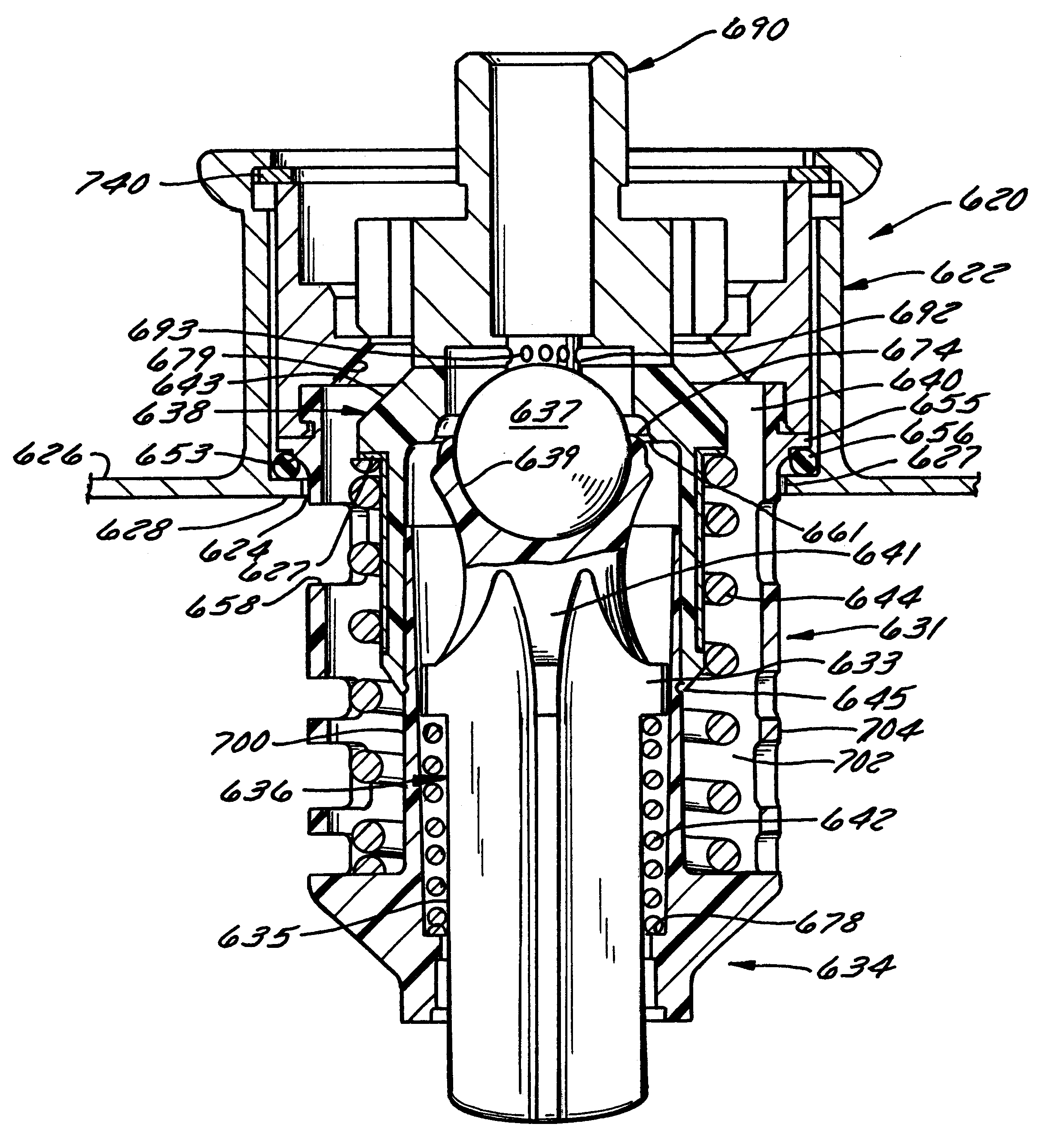
4. Description of Third Embodiment

Turning now to FIGS. 9-12, a valve assembly 320 constructed in accordance with a third embodiment of the invention is illustrated which is similar to the valve assembly 220 of the second embodiment. Components of the third embodiment corresponding to those of the second embodiment are, accordingly, designated by the same reference numerals, incremented by 100.

The valve assembly 320 of the third embodiment differs from the valve assembly 220 of the second embodiment primarily in that the dispensing tower 336 takes the form of an imperforate standpipe assembly rather than a perforated hollow pipe. The dispensing tower 336 therefore includes an upper head 361 of relatively large diameter and a lower shank 363 of relatively small diameter separated by a downwardly facing shoulder 369 on the head 361. An annular plate 362 is affixed to the bottom end portion of the shank 363 and serves the same function as the annular flange 262 of the second embodiment,...


PUM


Abstract

A valve assembly has (1) a riser pipe including a valve cup housing and portals blockable, and (2) a central tower which communicates with blockable pathways that pass both liquid and gas, and (3) a bi-directional valve member which controls separation of gas and liquid and directional flow in the chamber. A retainer assembly is provided on the outer peripheral surface of the valve cup so as to facilitate insertion of the valve cup into the container but so as to prevent the unintended removal of the valve cup from the container while still permitting selective valve cup removal when it is desired to do so. The retainer assembly preferably includes a protrusion and a pair of centering skids spaced about the outer periphery of the valve cup. The protrusion includes a radially tapered, vertical extending detent portion and a radially tapered, circumferentially extending ramp portion. The centering skids taper radially inwardly from vertically central portions thereof to the vertical end portions thereof. Upon simultaneous twisting and tilting of the valve cup relative to an annular member on the container such as the shoulder of a stub, the centering skids engage the annular member so as to take up the clearance between the valve cup and the annular member, and the protrusion ramps onto the annular member in a self-threading manner so as to circumferentially distort the valve cup and to permit the valve cup to be turned out of the container.

Description

BACKGROUND OF THE INVENTIONThe invention relates to valve arrangements or valve assemblies and, in particular, relates to valve assemblies for transportable containers of the type serving to store and distribute a liquid under pressure from a propellant gas. The liquid to be stored and dispensed could comprise a beverage, a concentrate, a plant protection agent, or virtually any other transportable liquid.The typical valve assembly of the above-mentioned type comprises (1) a ring-shaped stub secured in an upper opening of a container such as a barrel; (2) a valve housing; (3) a riser pipe arranged co-axially with an upper reception area in the valve housing such that the riser pipe and outlet valve can be displaced axially, against the biasing force of springs mounted within and about the valve housing, from an upper closed valve position to a lower open valve position; and (4) retaining parts which hold all parts in position within the stub. In previously-known valve assemblies of ...

Claims


Application Information

Patent Timeline
IPC IPC(8): B67D1/00B67D1/12B67D1/08
CPCB67D1/0802B67D1/125B67D1/0832Y10T137/314
Inventor AMIDZICH, BRADFORD G.
Owner VENT MATIC
Why Eureka
Try Eureka