
Color cathode ray tube

a cathode ray tube and color cathode technology, applied in the direction of cathode ray tubes/electron beam tubes, tubes with screens, electric discharge tubes, etc., can solve the problems of color purity degradation, insufficient portions, in fixed portions,

Inactive Publication Date: 2001-09-11
KK TOSHIBA
View PDF19 Cites 7 Cited by
  • Summary
  • Abstract
  • Description
  • Claims
  • Application Information

AI Technical Summary

Benefits of technology

The present invention has been developed in light of the above and its object is to provide a color cathode-ray tube capable of correcting color purity degradation due to thermal expansion without degrading the elastically supporting property of elastic support members incorporated therein.

Problems solved by technology

As a result, color purity degradation will occur.
This makes it difficult to secure, in the fixed portion, a sufficient portion necessary for spot welding.
As a result, the fixed portion is welded at a portion away from the acute-angle portion, which means that the acute-angle portion of the fixed portion, which is the root of the slop portion, cannot be firmly secured to the mask frame.
Similarly, depending upon the shape of the mask frame, the fixed portion of the holder cannot firmly be secured thereto.
The result is that the displacement of the mask frame along the tube axis is deviated from a desired set value while the mask frame thermally expands, and therefore the PD-2 cannot be corrected satisfactory.

Method used


Image

  • Color cathode ray tube
  • Color cathode ray tube
  • Color cathode ray tube

Examples


Embodiment Construction

Color cathode-ray tubes according to the embodiments of the invention will be described in detail with reference to the accompanying drawings.

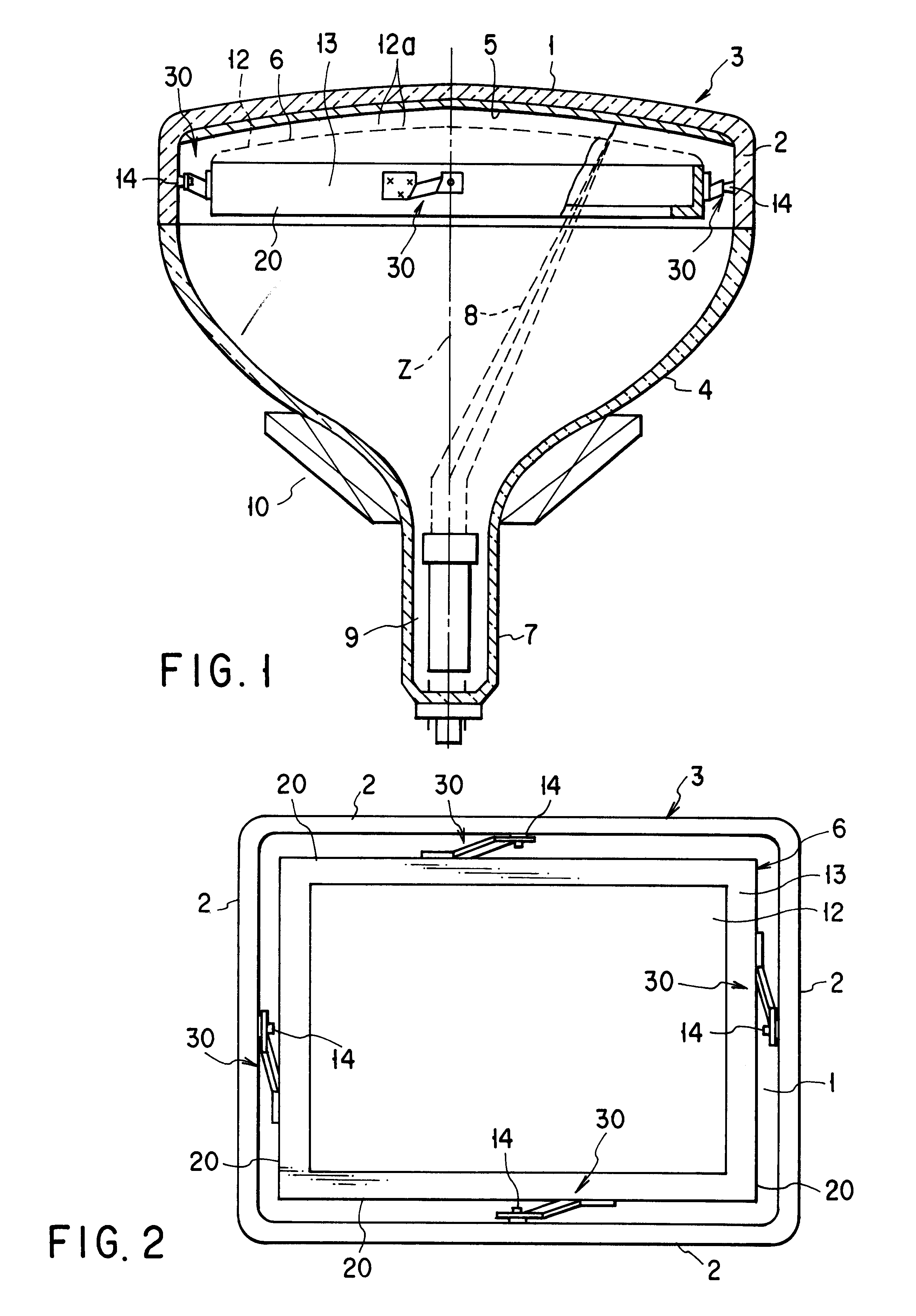
As is shown in FIGS. 1 and 2, a color cathode-ray tube is provided with a vacuum envelope, which comprises a substantially rectangular glass panel 3 and a funnel 4. The panel 3 has a substantially rectangular effective section 1, and four side wall sections 2 placed on a peripheral edge portion of the effective section 1. The funnel 4 is connected to the side wall sections 2. A tapered stud pin 14 protrudes inward from a center portion of the inner surface of each of the side wall sections 2.

A phosphor screen 5 formed of three-color phosphor layers, which are able to emit blue, green and red light, is provided on the inner surface of the effective section 1. A substantially rectangular shadow mask 6 is arranged inside the panel 3, opposed to the phosphor screen 5.

In the neck 7 of the funnel 4 is arranged an electron gun 9 that emits three elec...


PUM


Abstract

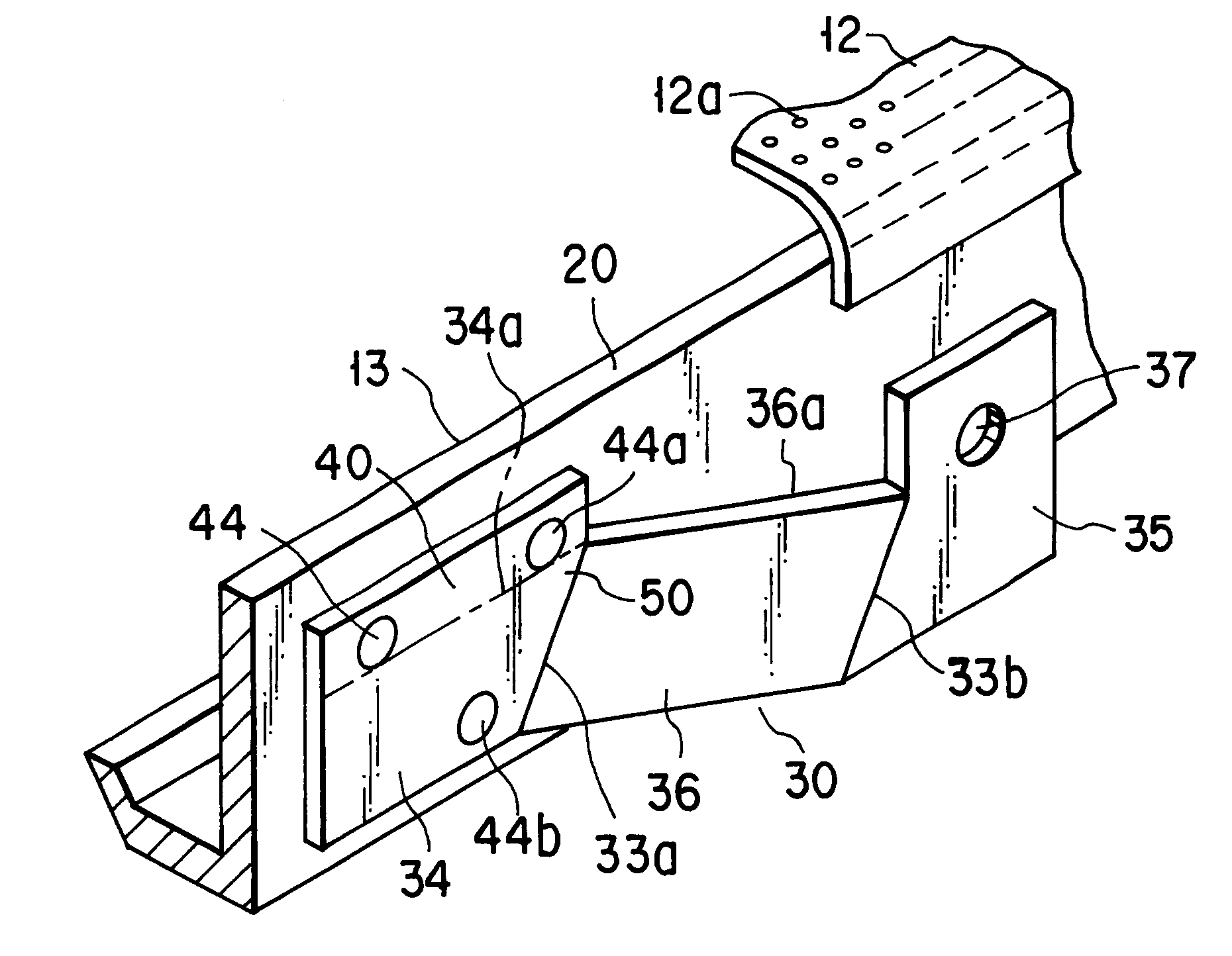
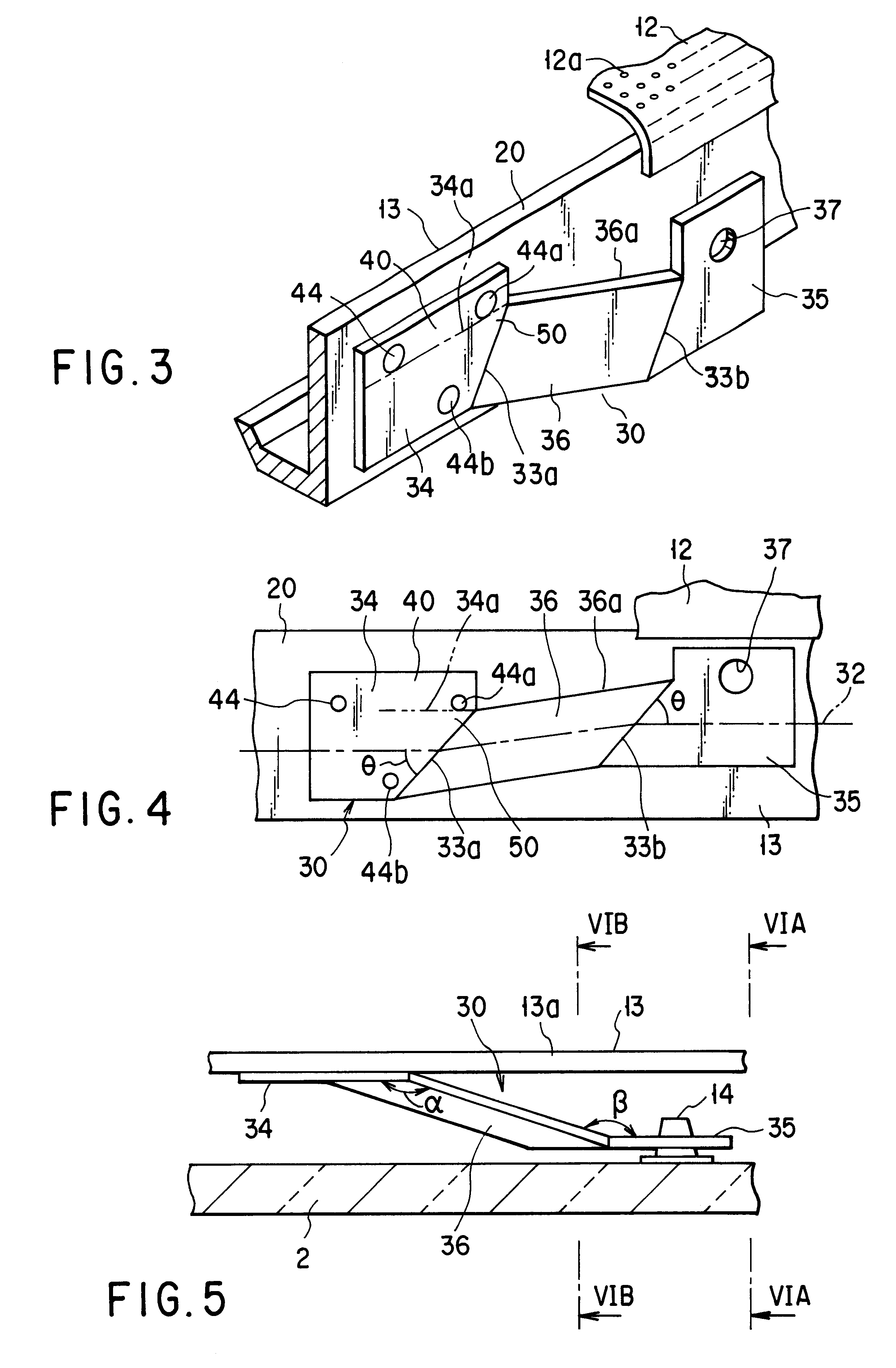
A holder 30 supporting a mask frame 13 is formed by bending an elongated, substantially rectangular metal plate in opposite directions along first and second bending lines 33a and 33b, such that the holder has an engagement portion 35 engaged with a corresponding stud pin, a fixed portion 34, and a slope portion 36 extending and inclined between the engagement portion and the fixed portion. When the mask frame has thermally expanded, the holder moves the mask frame toward a phosphor screen along the center axis of a face panel. The fixed portion 34 has a projection 40 projecting from the vicinity of an acute-angle portion 50 which is defined by a side edge of the fixed portion and the first bending line. The fixed portion is fixed to the mask frame in the vicinity of the first bending line by welding at least a part of the projection to the mask frame.

Description

This application is the national phase of international application PCT / JP98 / 04048 filed Sep. 9, 1998 which designated the U.S.This invention relates to a color cathode-ray tube, and more particularly, to a color cathode-ray tube having a shadow mask supported by elastic support members which are provided for compensating deviation of beam landing due to thermal expansion of the shadow mask or a face panel.In general, a color cathode-ray tube is provided with an envelope that includes a rectangular face panel having side wall sections on a peripheral edge portion of an effective section thereof, and a funnel coupled to the side wall sections of the panel. A phosphor screen comprising three color phosphor layers which are able to emit blue, green and red light is formed on the inner surface of the effective section of the face panel. In the envelope, a substantially rectangular shadow mask is opposed to the inside of the face panel. An electron gun for emitting three electron beams i...

Claims


Application Information

Patent Timeline
Patent Type & Authority Patents(United States)
IPC IPC(8): H01J29/07H01J29/02H01J31/20
CPCH01J29/073H01J29/02
Inventor TAKANO, NAOHISAYOKOTA, MASAHIRO
Owner KK TOSHIBA
Learn More