
Device and process for adsorption or chemisorption of gaseous constituents from a gas flow

a gas flow and gaseous constituent technology, applied in gravity filters, filter regeneration, dispersed particle filtration, etc., can solve the problem of difficult maintenance of the dust return ra

Inactive Publication Date: 2001-09-18
VOL ROLL UMWELTTECHNIK AG
View PDF15 Cites 21 Cited by
  • Summary
  • Abstract
  • Description
  • Claims
  • Application Information

AI Technical Summary

Benefits of technology

The unfiltered-gas duct, which can be adjusted in the filter chamber, in particular in the vertical direction, has the advantage that the dust located in the lower area of the collection chamber is picked up by the unfiltered gas flowing in, is thrown upward and, in this way, is recirculated in the filter chamber. The adjustability of the position of the unfiltered-gas duct makes it possible to set the amount of dust which is recirculated. If the unfiltered-gas duct opens out at a relatively low level into the filter chamber, a relatively large proportion of the dust which has collected in the lower area of the filter chamber is picked up and recirculated. If the unfiltered-gas duct opens out at a relatively high level in the filter chamber, the unfiltered gas flowing in has scarcely any entraining action on the dust which is collected in the lower area of the filter chamber, with the result that a relatively small amount of dust is recirculated in the filter chamber. The position of the unfiltered-gas duct, and consequently the amount of dust which is recirculated, can be set using a drive device arranged outside the filter chamber. In addition, a discharge device is arranged in the lower area of the filter chamber allowing the accumulated dust to be removed from the filter chamber in a controllable manner. This discharge device makes it possible to set the total amount of dust or adsorbent located in the filter chamber.
The filter device according to the invention thus makes it possible to set the total amount of dust located in the filter chamber using the discharge device. Moreover, by adjusting the unfiltered-gas duct, it is possible to set the flow of dust, i.e., the mass of dust which is recirculated per unit time in the filter device. In addition to these advantageous setting options, the filter device according to the invention has the advantage that it does not have to be shut down in order for the dust to be removed. The high dust density which is possible or the high recirculation rate which is possible in the filter chamber makes it possible to clean the unfiltered gas very well.
In an advantageous configuration, ceramic filter candles are arranged in the filter device, providing the additional advantage that the device can be operated with flue-gas temperatures of up to 850.degree. C.

Problems solved by technology

A drawback of this device and process is that the dust return rate is difficult to maintain, since it is determined by the amount of dust located in the separation plant.
A further drawback is the fact that the dusts can only be removed off-line, with the result that a filter chamber has to be taken out of on-line mode into off-line mode, then the filter chamber has to be emptied, in order for the filter chamber then to be returned to the on-line mode.

Method used


Image

  • Device and process for adsorption or chemisorption of gaseous constituents from a gas flow
  • Device and process for adsorption or chemisorption of gaseous constituents from a gas flow
  • Device and process for adsorption or chemisorption of gaseous constituents from a gas flow

Examples


Embodiment Construction

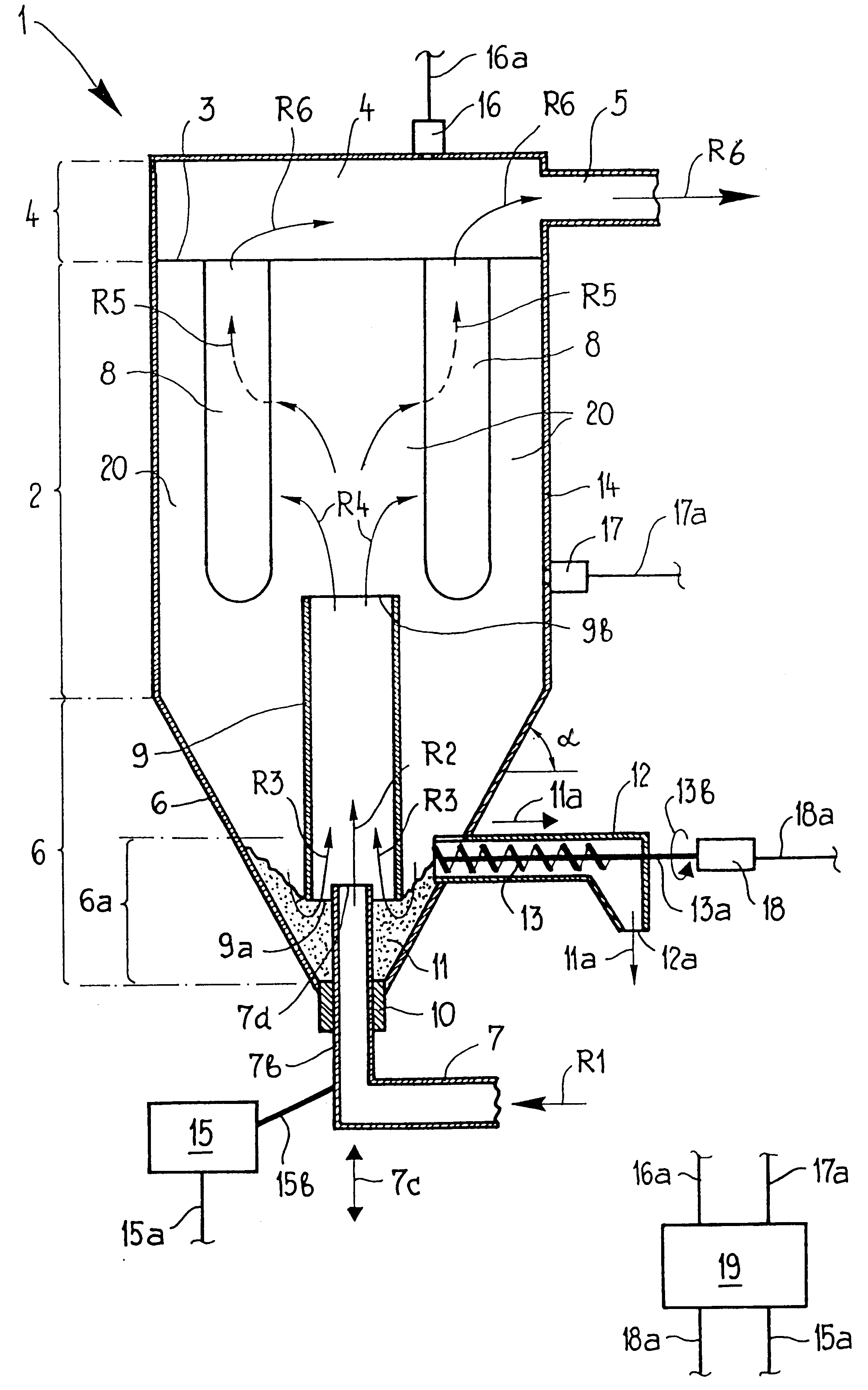
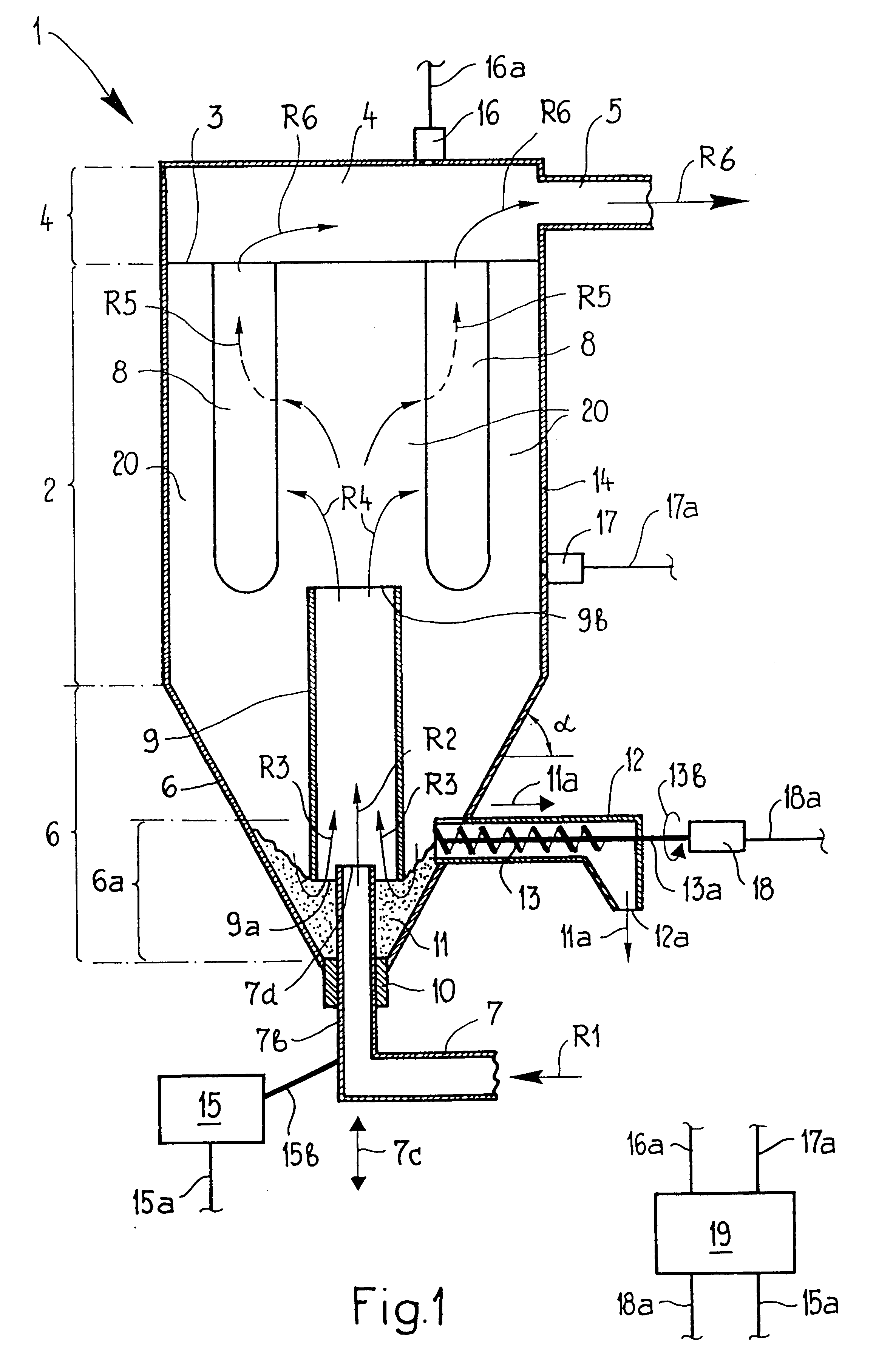
FIG. 1 shows a filter device 1 which comprises a filter chamber 2, also referred to as a separation chamber, which is open at the bottom, leading into a collection chamber 6. In its lower area 6a, the collection chamber 6 has an interior which narrows toward the bottom and in the embodiment illustrated is designed so as to run conically. A sealing element 10, in which an unfiltered-gas duct 7b, 7 is mounted in such a manner that it can be displaced in direction 7c, is arranged at the very bottom of the collection chamber 6. In the example illustrated, the direction of displacement 7c runs in the vertical direction. Outside the filter device 1, there is a drive device 15 which can be activated via an electric cable 15a, is coupled to the unfiltered-gas duct 7b via a mechanical means 15b and allows the height of the unfiltered-gas duct 7b to be adjusted in direction 7c. This height adjustment adjusts the position of the outlet opening 7d of the unfiltered gas duct 7b in the collection...


PUM

PropertyMeasurementUnit
flue-gas temperaturesaaaaaaaaaa
structural heightaaaaaaaaaa
adsorptionaaaaaaaaaa

Abstract

A filter device for adsorption of gaseous constituents from a gas flow includes a filter chamber with filters arranged therein, a clean-gas chamber connected to the first chamber in a fluid-conducting manner via the filters, and a collection chamber arranged beneath the filter chamber, is open toward the filter chamber and has an interior which narrows toward the bottom. An unfiltered-gas duct which leads from the outside, is arranged in the lower area of the collection chamber in such a manner that it can be adjusted in the direction toward the filters. A dust-discharge device, which leads toward the outside, is arranged in the lower area.

Description

1. Field of the InventionThe invention relates to a device for adsorption or chemisorption of gaseous constituents from a gas flow. The invention furthermore relates to a process for adsorption or chemisorption of gaseous constituents from a gas flow.2. Description of the Related ArtThe publication EP 0,476,300 B1 has disclosed a device and a process for adsorption or chemisorption of gaseous constituents from a gas flow. A drawback of this device and process is that the dust return rate is difficult to maintain, since it is determined by the amount of dust located in the separation plant. A further drawback is the fact that the dusts can only be removed off-line, with the result that a filter chamber has to be taken out of on-line mode into off-line mode, then the filter chamber has to be emptied, in order for the filter chamber then to be returned to the on-line mode.The object of the present invention is to provide a device which is economically more advantageous and a process wh...

Claims


Application Information

Patent Timeline
Patent Type & Authority Patents(United States)
IPC IPC(8): B01D45/02B01D45/00B01D53/10B01D53/06B01D39/20B01D46/00B01D46/24
CPCB01D53/10B01D45/02
Inventor KOLLER, FELIXFREY, RUDOLFFLURY, RAINER
Owner VOL ROLL UMWELTTECHNIK AG
Learn More