
Wavelength selective switching element

a technology of selective switching and above-described switches, which is applied in the direction of optical elements, instruments, optical waveguide light guides, etc., can solve the problems of large power loss, high cost, and difficult re-configuration of devices,

Inactive Publication Date: 2001-09-18
TELEFON AB LM ERICSSON (PUBL)
View PDF3 Cites 9 Cited by
  • Summary
  • Abstract
  • Description
  • Claims
  • Application Information

AI Technical Summary

Benefits of technology

The object of the present invention is to obtain a wavelength selective switch, in which each wavelength can be switched independently of the rest of the wavelengths and to all possible selections of outputs, which by its structure is so simple and compact as possible, so that the manufacturing cost thereby can be reduced compared to known techniques.
An advantage of the present invention is that the power loss can be kept relatively low.
Another advantage of the present invention is that its performance, such as cross-talk etc. can be improved compared to prior art.

Problems solved by technology

However, the above disclosed switch cannot be used as a wavelength selective switch.
This type of device is, relatively hard to re-configure, i.e. inflexible.
The problems with above the described technology as regards wavelength selective switches is that these require very large complicated structures or several components, which results in large power losses and a high cost.
One problem with known wavelength selective switches is that these contribute to large power losses.
Another problem with known wavelength selective switches is that known wavelength selective switches have a relatively complicated structure and in all known cases a relatively large number of different elements.
Yet another problem is that known wavelength selective switches are relatively expensive to manufacture based on above disclosed complicated structure and the number of comprised components.

Method used


Image

  • Wavelength selective switching element
  • Wavelength selective switching element
  • Wavelength selective switching element

Examples


Embodiment Construction

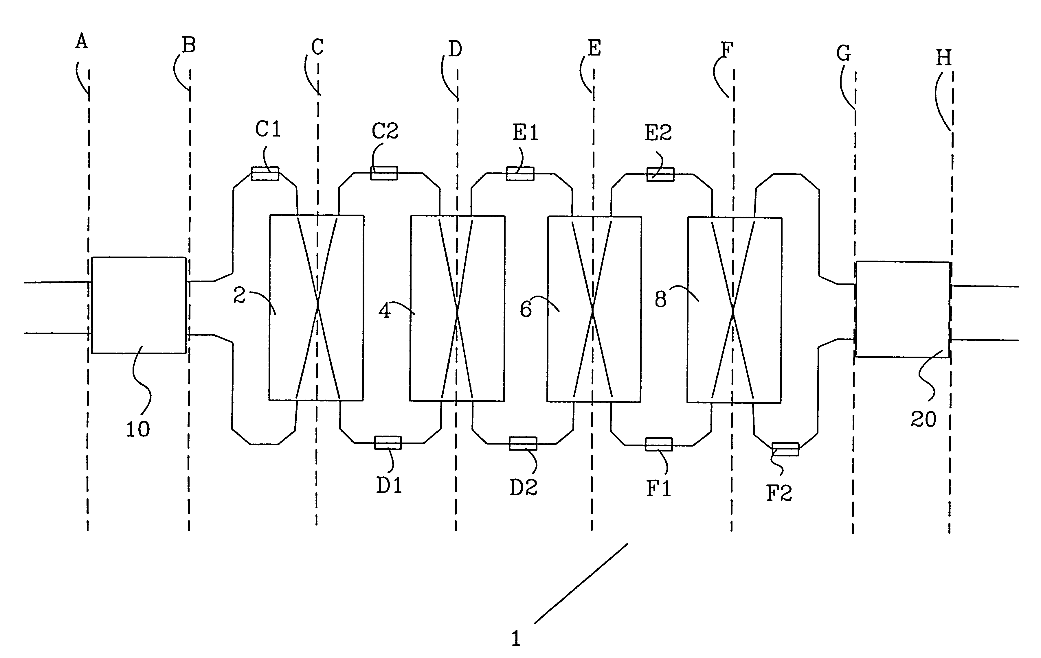
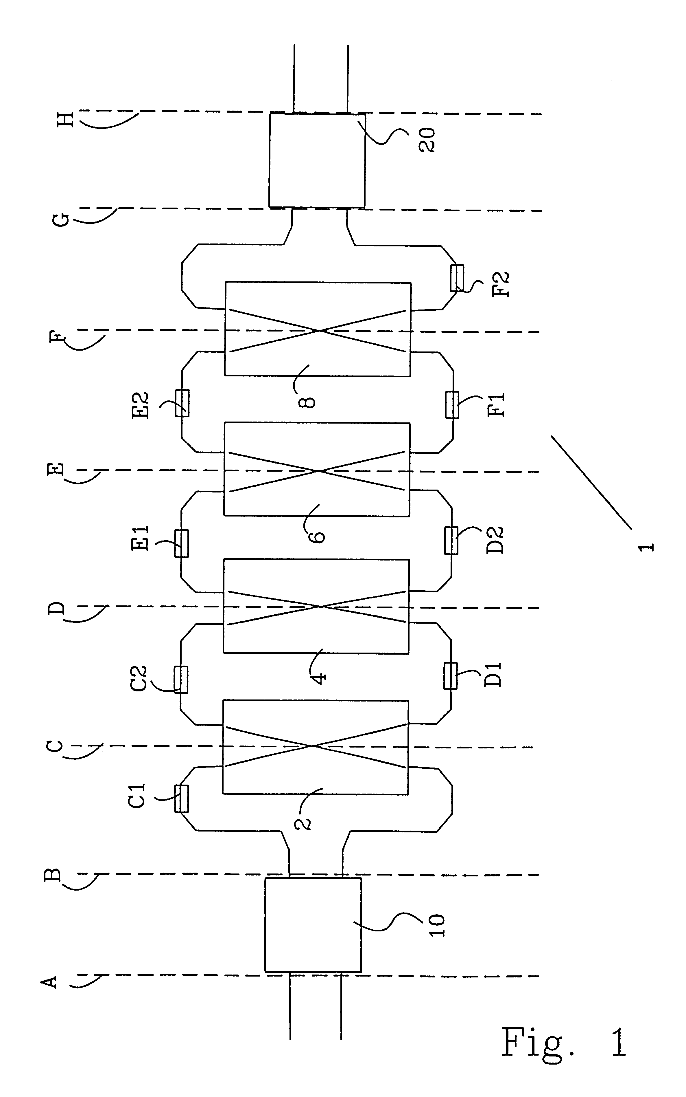
FIG. 1 shows an embodiment of a wavelength selective switch 1 according to the invention. The wavelength selective switch 1 comprises two multi-mode waveguides 10, 20, four wavelength selective cross-connection structures 2, 4, 6, 8, eight phase control elements C1, C2, D1, D2, E1, E2, F1, F2, ten connection waveguides and access waveguides provided on both of the multi-mode waveguides 10, 20 and on the cross-connection structures 2, 4, 6, 8.

An optical signal comprising a number of different wavelengths is excited into the access wave guide provided on a first side of a first multi-mode waveguide 10. The optical signal is transmitted through the multi-mode waveguide 10 and projected on the access waveguides provided on an opposite side compared to where the optical signal was excited. The signal is projected depending on length-width ratio on the multi-mode waveguide 10 and the arrangement of the access waveguides. Assume that length-width ratio is like that an optical signal which ...


PUM


Abstract

The invention relates to a device and a method for switching optical wavelength channels. Said optical wavelength channels are introduced into at least one access waveguide provided on a first side of a first multi-mode waveguide (10). Subsequently, the wavelength channels are transmitted through said multi-mode waveguide (10) and projected on at least two connection waveguides provided on the opposite side. Subsequently, the optical wavelength channels are transmitted through the connection waveguides. For each wavelength selective cross-connection structure (2, 4, 6, 8) the phase is changed for a reflecting wavelength of two phase control elements (C1, C2, D1, D2, E1, E2, F1, F2) arranged in a first and a second connection waveguide on a first side of said wavelength selective cross-connection structure (2, 4, 6, 8), simultaneously as at a second side of said wavelength selective cross-connection structure (2, 4, 6, 8) said reflecting wavelength phase remains relatively unchanged. For each wavelength selective cross-connection structure (2, 4, 6, 8) the phase is changed for transmitting wavelengths once in a first and a second direction per wavelength selective cross-connection structure (2, 4, 6, 8). The phase difference between the optical signal in each access waveguide provided on the first side of the second multi-mode waveguide (20) determines where the optical signal is focused on the opposite side.

Description

The invention relates to an optical wavelength selective device, and more particularly to a wavelength selective switch for re-routing wavelength channels in an optical network, in which each wavelength channel can be re-routed separately and independently on the other wavelength channels. The invention also relates to a method for re-routing wavelength channels in an optical network.STATE OF THE ARTTo be able to further increase the capacity on already existing optical networks, there are a number of different known methods. One way is to use so-called wavelength division multiplex (WDM) technology for improving the degree of operation of available bandwidth connection an optical fibre in the optical network. To be able to increase the flexibility of the network, devices which can provide re-routing of traffic in the optical network are necessary. Such devices for re-routing traffic are also suitable for employing the network in the most effective way as possible and at interruptio...

Claims


Application Information

Patent Timeline
IPC IPC(8): G02B6/12G02B6/34G02F1/313G02F1/29H04Q11/00H04B10/27H04B10/291H04Q3/52
CPCG02B6/12007G02B6/29317G02B6/29355G02F1/3136H04Q11/0005G02B6/29395G02B6/29353H04Q2011/0022G02F2201/307G02F2203/05H04B10/2581H04B10/25
Inventor AUGUSTSSON, TORSTEN
Owner TELEFON AB LM ERICSSON (PUBL)
Learn More