Eureka AIR delivers breakthrough ideas for toughest innovation challenges, trusted by R&D personnel around the world.

High severity, low conversion hydrocracking process

a hydrocracking and high severity technology, applied in the direction of hydrocarbon oil cracking, hydrocarbon oil treatment, effluent separation, etc., can solve the problem of low conversion process in general

Inactive Publication Date: 2001-09-25
UOP LLC
View PDF4 Cites 32 Cited by
  • Summary
  • Abstract
  • Description
  • Claims
  • Application Information

AI Technical Summary

Problems solved by technology

Bypassing hydrocarbons around the hydrocracking zone results in an overall low conversion process.

Method used


Image

  • High severity, low conversion hydrocracking process

Examples


Embodiment Construction

Much of the crude petroleum which is produced cannot be used directly as a modern fuel or petrochemical feed stock. It must be refined to remove sulfur and nitrogen which would increase air pollution if present in a fuel. It must also be refined to reduce the average molecular weight of the heavier components of the crude such that the volatility or flow characteristics of fuels are met. Finally, refining is necessary to meet quality standards for specific hydrocarbon products and to convert the petroleum derived compounds into suitable feedstocks for petrochemical plants. The required refining can be done in several ways. One of the more established methods employs sequential catalytic hydrotreating and catalytic hydrocracking. This is a well developed process used in a number of petroleum refineries.

Typical feedstocks include virtually any heavy mineral (petroleum derived) or synthetic oil fraction having boiling points above about 400.degree. F. (204.degree. C.). Thus, such feeds...


PUM


Abstract

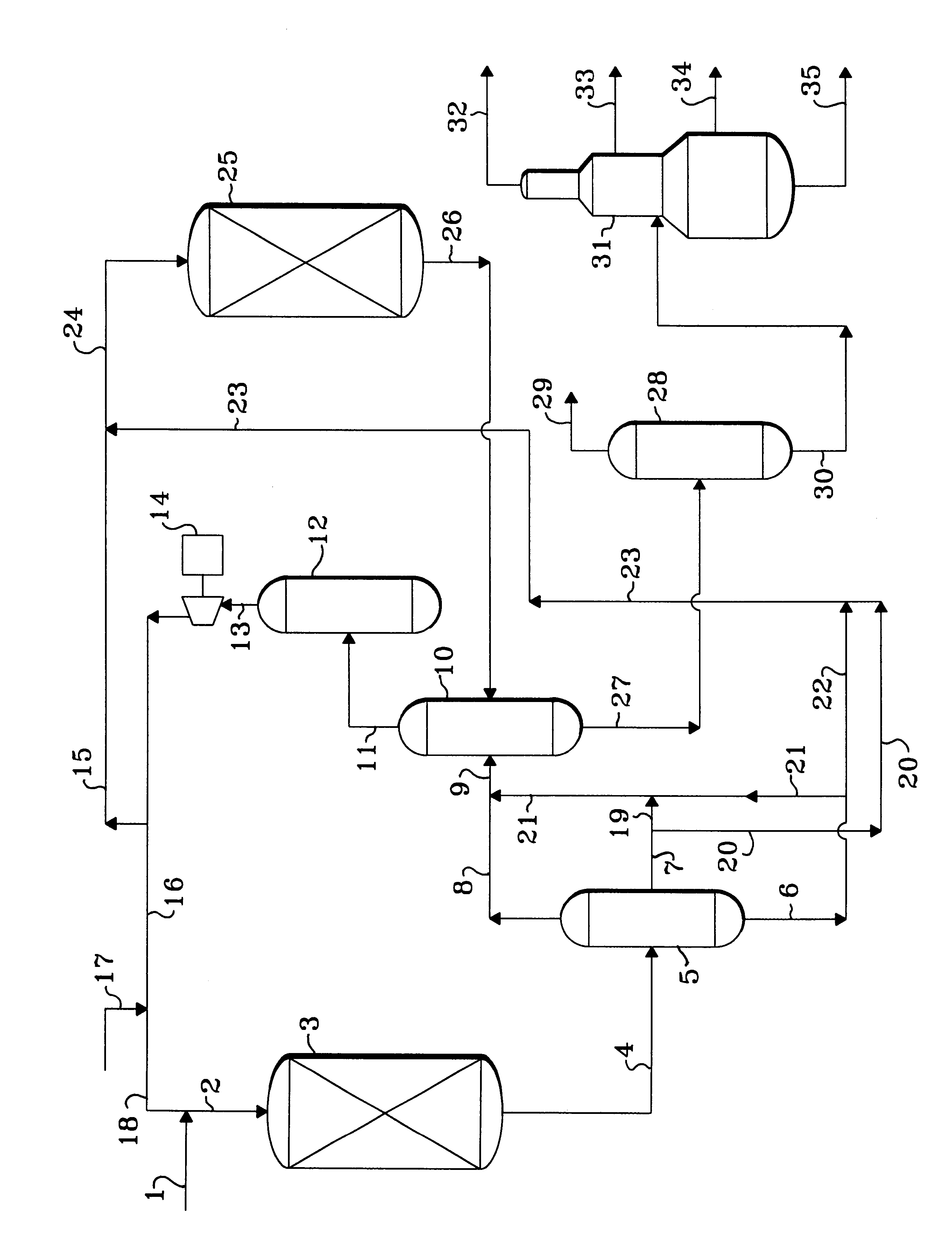
A feed stream is first processed in a hydrotreating reaction zone and then the effluent is separated into three fractions in an augmented first high pressure separator. Controlled portions of the middle and heavy hydrocarbon fractions are passed into a high severity hydrocracking zone, while the remaining portions of these two fractions are passed into a second high pressure separator for recovery. The effluent of the hydrocracking zone is also fed to the second high pressure separator.

Description

The invention relates to a hydrocarbon conversion process referred to in the art as hydrocracking, which is used commercially in petroleum refineries to reduce the average molecular weight of heavy or middle fractions of crude oil. The invention more directly relates to an integrated hydrotreating / hydrocracking process which has a specific product separation arrangement. The invention is specifically related to the separation of the effluent of the hydrotreating zone using sequential high pressure separators.Large quantities of petroleum derived hydrocarbons are converted into higher value hydrocarbon fractions used as motor fuel by a refining process referred to as hydrocracking. In this process the heavy feed is contacted with a fixed bed of a solid catalyst in the presence of hydrogen at conditions of high temperature and pressure which results in a substantial portion of the molecules of the feed stream being broken down into molecules of smaller size and greater volatility. The...

Claims


Application Information

Patent Timeline
IPC IPC(8): C10G65/12C10G49/22C10G49/00C10G65/00
CPCC10G65/12C10G49/22
Inventor THAKKAR, VASANT P.ANDERLE, CHRISTOPHER J.GALA, HEMANT B.
Owner UOP LLC
Why Eureka
Eureka Blog
Learn More