
Electrostrictive or piezoelectric actuator device with a stroke amplifying transmission mechanism

a transmission mechanism and actuator technology, applied in piezoelectric/electrostrictive devices, piezoelectric/electrostrictive devices, device details, etc., can solve the problems of increasing the material of the hinge due to the bending movement, the stiffness of the bending hinge, and the insufficient multiplication of displacement achieved by such an electrostrictive or piezoelectric stack element for many applications

Inactive Publication Date: 2001-09-25
EADS DEUT GMBH
View PDF9 Cites 146 Cited by
  • Summary
  • Abstract
  • Description
  • Claims
  • Application Information

AI Technical Summary

Benefits of technology

Thus, according to the invention, the individual flexible joints are divided respectively into a plurality of hinge members, and at least one of the frame members connected to each flexible joint is divided into a respective plurality of individual link rods. Otherwise, the structural parameters of the transmission mechanism, for example especially the total cross-sectional area, and the total tensile strength and stiffness of the flexible joints, can be the same as an arrangement using single flexible joints and only single link rods, because these parameters are directly determined from the load characteristics. Nonetheless, due to the inventive arrangement, the bending stiffness of the flexible joints is reduced significantly, namely proportionally to the square of the respectively selected degree of division of the flexible joints into individual hinge members. As a result of this reduction of the joint stiffness, the elastic return force or counter force exerted by the flexible joints on the transmission mechanism countering the deformation force of the actuator element is also significantly reduced, and the useful stroke of the actuator device is substantially increased. As a further beneficial effect, the outer fiber strain of the material forming the hinge members, relative to the bending angle, is similarly reduced, because the thickness of each individual hinge member is reduced. For this reason, the overall operating life time of the actuating device is considerably improved.
A preferred embodiment of the invention uses a two-fold division of the flexible joints and the divided frame members. Namely, each flexible joint includes two parallel hinge members, and each divided frame member includes two individual link rods. In such an embodiment, the bending stiffness of the flexible joints is already reduced by 75%, and the outer fiber strain in the hinge members is reduced by 50%, in comparison to an otherwise similarly configured and dimensioned bending joint linkage using only unitary flexible joints and unitary frame members.
In order to further reduce the bending stiffness and the outer fiber strain of the material of the flexible joints of the actuator device, an even finer division rather than a two-fold division can be used for the flexible joints and the divided frame members. In this case also, the individual link rods forming the divided frame members preferably have an equal length and are preferably arranged parallel to one another to ensure a forceless parallel guidance of the transmission mechanism and particularly the output members. Namely, the individual parallel link rods of each divided frame member, which are connected together integrally at the ends thereof by the unitary frame members, form respective parallelogram rod linkages that necessarily hold the two unitary frame members, i.e. a respective output member and a respective actuator end block member, parallel to each other.
Especially for use in dynamic actuator applications, it is advantageous to provide a pre-biasing spring effective on the transmission mechanism so as to pre-load the transmission mechanism in such a direction as to pre-compress the actuator element. This arrangement avoids external tension loads from being effective on the solid state actuator element itself, which is very load sensitive in this regard.
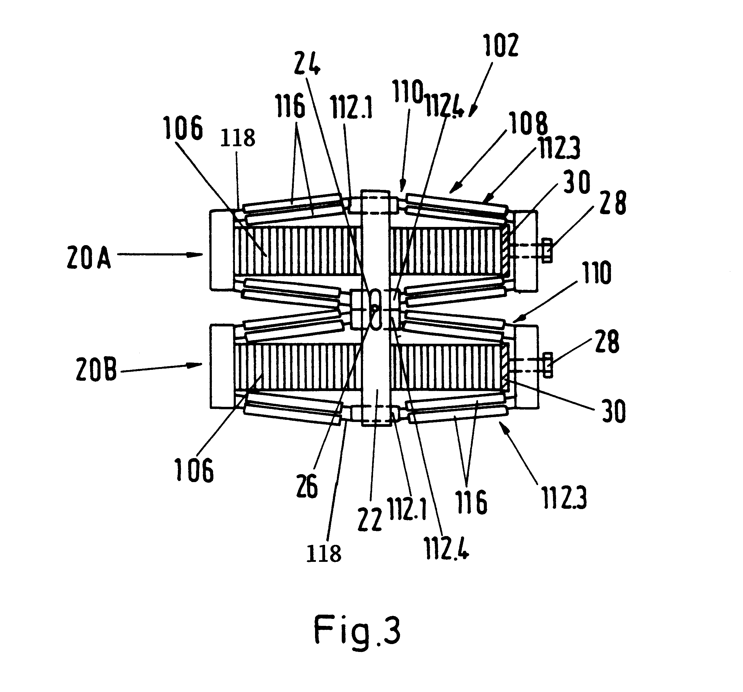
An alternative embodiment for avoiding external tension loads from affecting the actuator element involves two mechanically serially arranged and interconnected actuators that respectively comprise an actuator element and a transmission mechanism, whereby the actuator elements of the two actuators are oppositely electrically energized, so that one is elongated while the other is contracted. The two transmission mechanisms of the two actuators are both connected to a common output member that couples together the outputs of the two actuators. Such an actuator device has the advantage that thermal elongations are compensated, and a pre-stressing spring is not necessary. Furthermore, the output force of the two actuators is added together, while maintaining the useful working stroke of an individual actuator.

Problems solved by technology

However, even the multiplied displacement achieved by such an electrostrictive or piezoelectric stack element is inadequate for many applications.
This simultaneously causes the disadvantage that the overall bending stiffness of the bending hinge, and also the outer fiber strain resulting in the material of the hinge due to the bending movement, increase sharply with increasing cross-sectional area of the hinge joint.
As a result, the hinge joints, which are appropriately dimensioned for the prevailing loads, cause an elastic return force and bending resistance that acts against the electrically induced length variation of the actuator element and therefore noticeably reduces the effective stroke of the actuator device.
This arrangement avoids external tension loads from being effective on the solid state actuator element itself, which is very load sensitive in this regard.

Method used


Image

  • Electrostrictive or piezoelectric actuator device with a stroke amplifying transmission mechanism
  • Electrostrictive or piezoelectric actuator device with a stroke amplifying transmission mechanism
  • Electrostrictive or piezoelectric actuator device with a stroke amplifying transmission mechanism

Examples


Embodiment Construction

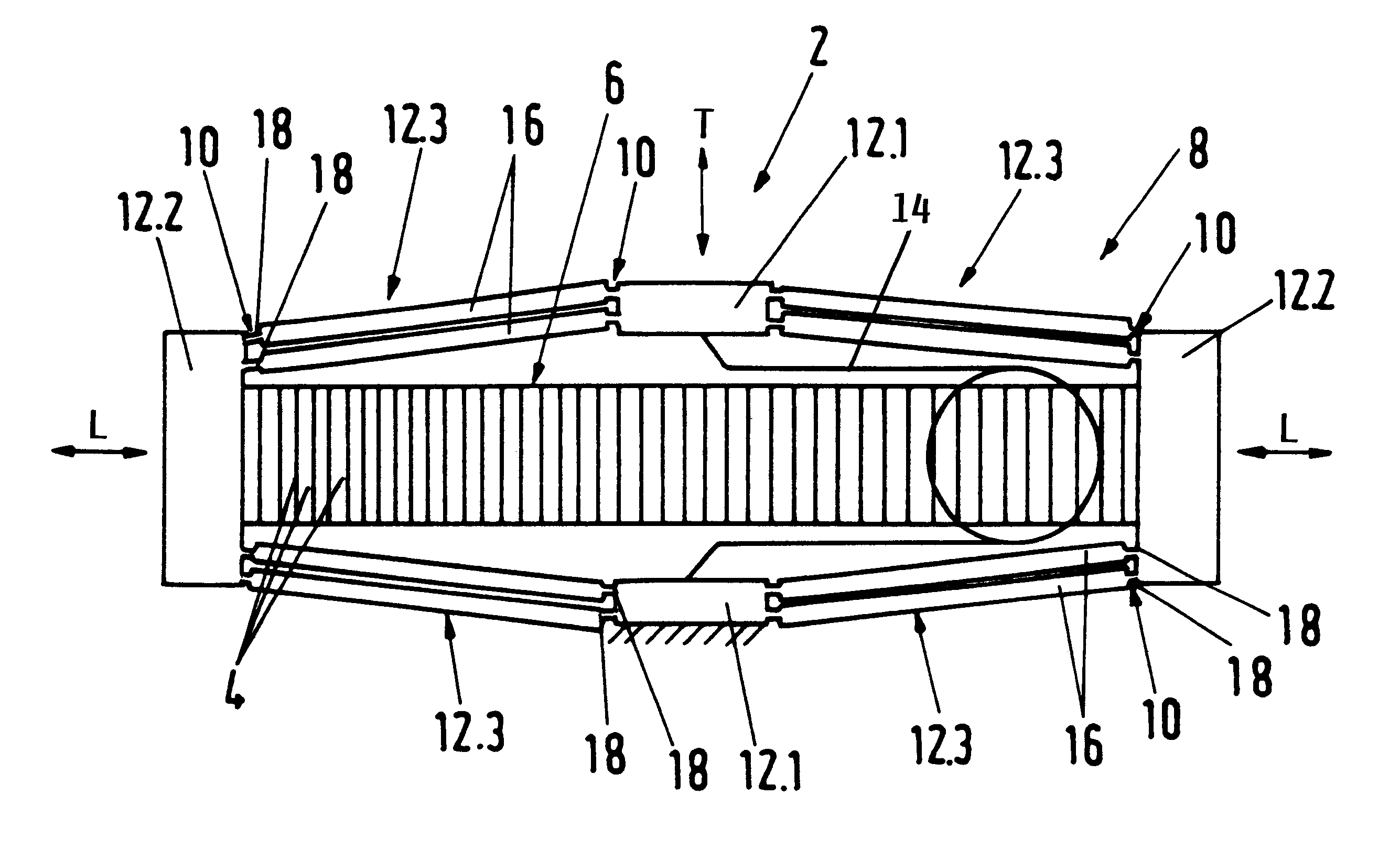
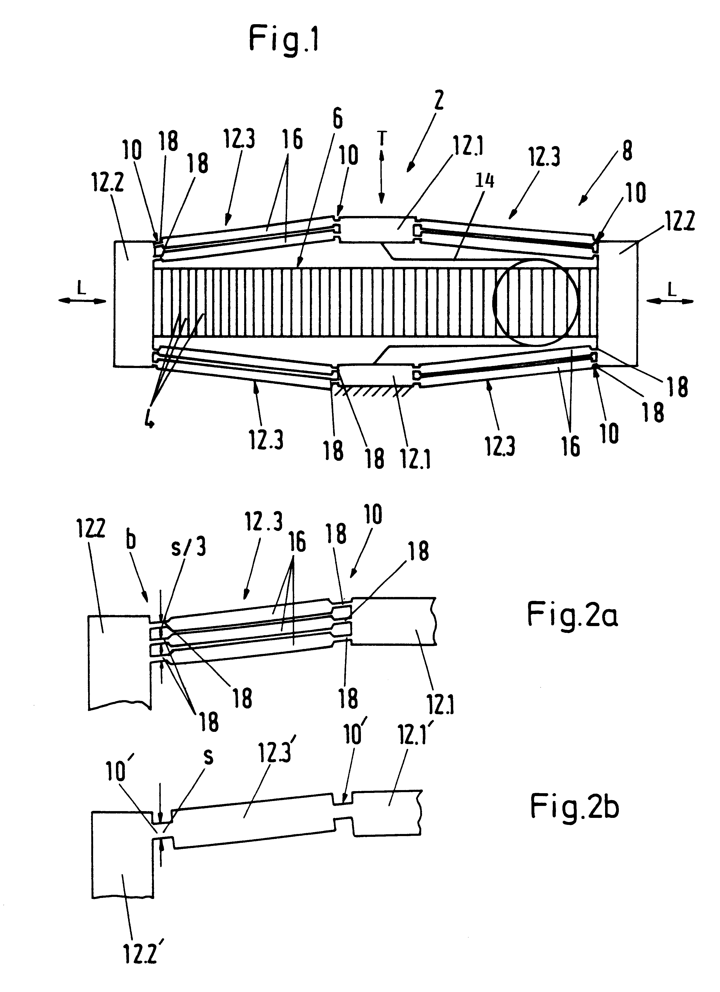
The solid state actuator device 2 shown in FIG. 1 comprises an electrically strainable solid state actuator element 6 and a transmission mechanism 8 in the form of an octagonal rod linkage frame that surrounds the actuator element 6. The actuator element 6 comprises a laminated stack of layers 4 of an electrically strainable solid state material, which is preferably a piezoelectric material but may alternatively be an electrostrictive material. The transmission mechanism 8 comprises rigid frame members 12 that are respectively connected to each other by elastically flexible joints 10.

The frame members 12 include four unitary frame members 12.1 and 12.2, alternatingly arranged with four divided frame members 12.3 to form the sides of the octagon. The four unitary frame members include two actuator element end block members 12.2 arranged at the lengthwise ends of the actuator element 6, and two output members 12.1 arranged laterally to the sides of the actuator element 6 on a plane be...


PUM


Abstract

An actuator device (2) includes a piezoelectric or electro-strictive solid state actuator element (6) that is elongated upon application of an electric voltage thereto, and a transmission mechanism (8) that amplifies the stroke displacement of the actuator element. The transmission mechanism (8) includes a plurality of rigid frame members (12), including unitary frame members (12.1, 12.2) and divided frame members (12.3), and elastically flexible joints (10) that respectively interconnect the frame members. Each one of the divided frame members (12.3) is made up of a plurality of separate parallel link rods (16). Each flexible joint (10) is made up of a plurality of individual parallel hinge members (18) that respectively connect an end of each one of the link rods (16) to the adjacent unitary frame member (12.1, 12.2). By this division of the flexible joints and of the divided frame members into parallel sub-components, the cross-sectional thickness of each individual hinge member is reduced, and thereby the bending stiffness and the outer fiber strain of the material of the hinge members is significantly reduced while providing the same total tensile strength and tensile stiffness. The link rods of each divided frame member effectively form a parallelogram linkage for moving and guiding the output members (12.1) in a parallel manner.

Description

The invention relates to an electrostrictive or piezoelectric actuator device including a solid state actuator element that has a variable length upon application of an electrical voltage, and including a transmission mechanism that amplifies the displacement or stroke movements of the actuator element, wherein the transmission mechanism comprises rigid frame members connected to each other by elastically flexible joints.BACKGROUND INFORMATIONActuator devices of the above mentioned general type typically include a solid state electrostrictive or piezoelectric element as an actuator, which becomes elongated in a lengthwise direction due to strain induced in the electrostrictive or piezoelectric material upon application of an electrical voltage thereto. The present specification applies to both electrostrictive and piezo-electric actuator elements, which will generally be referred to as electrically strainable solid state actuator elements, which comprise corresponding electrically s...

Claims


Application Information

Patent Timeline
IPC IPC(8): H01L41/09F16H21/02H02N2/00
CPCH02N2/043
Inventor JAENKER, PETER
Owner EADS DEUT GMBH
Learn More