Wavelength-locked external cavity lasers with an integrated modulator

a laser and wavelength-locked technology, applied in the field of external cavity lasers, can solve the problems of complex fabrication of filter-locked lasers, inability to directly modulate filter-locked lasers at a high bit rate, and inability to directly modulate filter-locked lasers at 2.5 gbit/sec and beyond

a laser and wavelength-locked technology, applied in the field of external cavity lasers, can solve the problems of complex fabrication of filter-locked lasers, inability to directly modulate filter-locked lasers at a high bit rate, and inability to directly modulate filter-locked lasers at 2.5 gbit/sec and beyond

US6295308B1Inactive Publication Date: 2001-09-25OCLARO NORTH AMERICA

Image

  • Wavelength-locked external cavity lasers with an integrated modulator
  • Wavelength-locked external cavity lasers with an integrated modulator
  • Wavelength-locked external cavity lasers with an integrated modulator

Examples


example 1

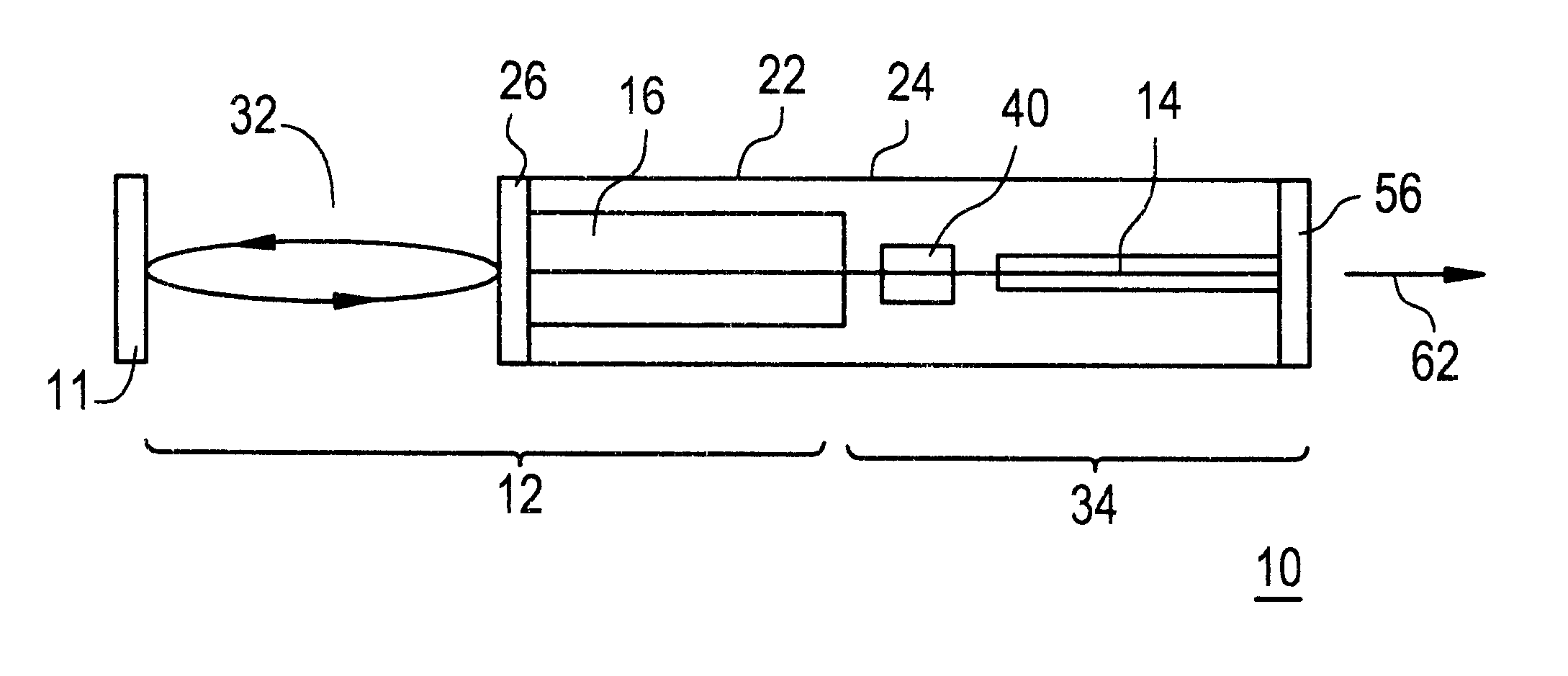
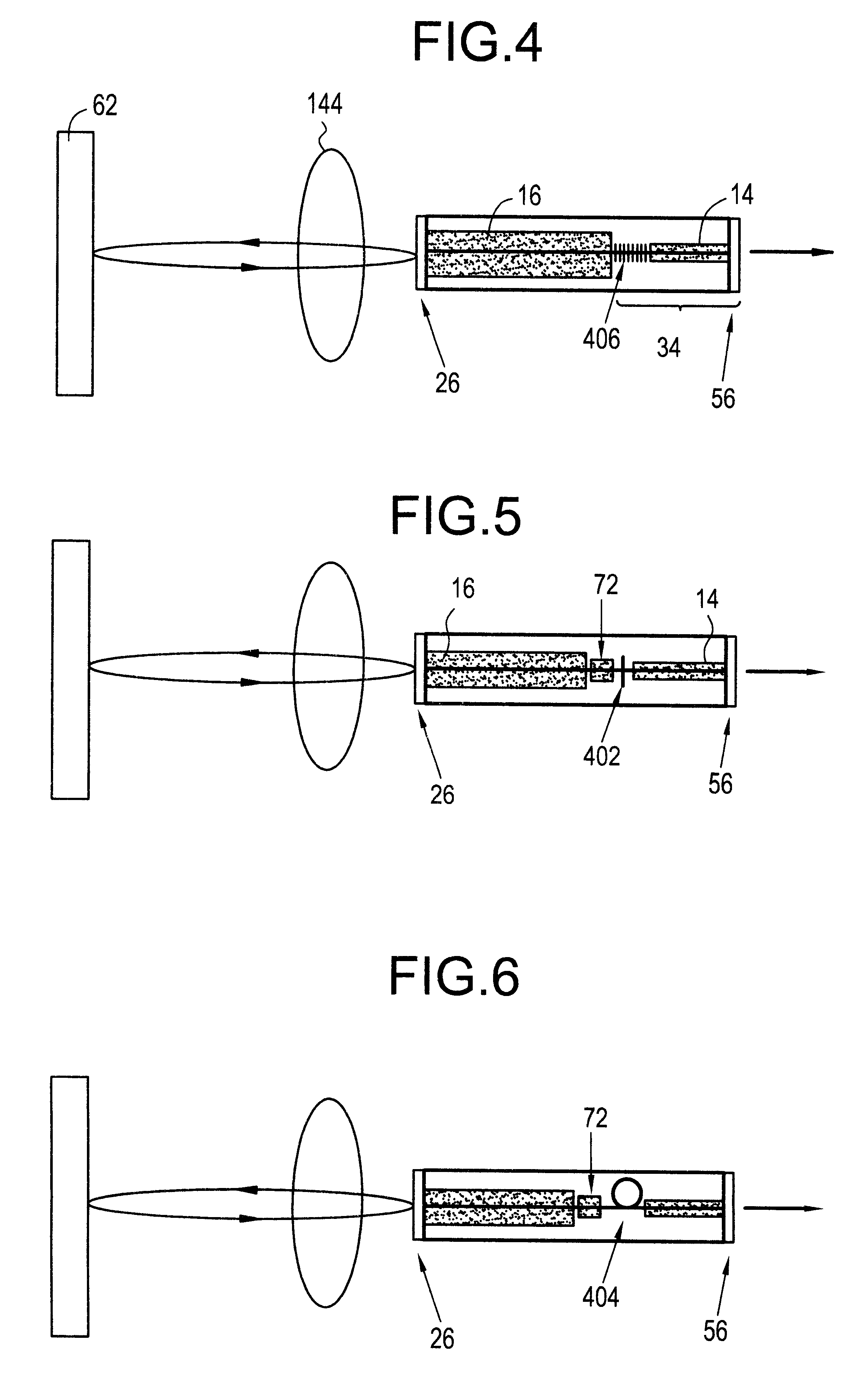
The narrow-band internal partial reflector 40 of FIG. 1 is provided by the distributed Bragg reflector (DBR) 406 in the passive waveguide region 34 in FIG. 4. The reflection band width (.DELTA..lambda..sub.B) can be written as ##EQU1##

where .kappa. is the grating coupling coefficient, .lambda. is the wavelength and n is the refractive index. The reflection bandwidth is about 2 nm assuming that .lambda.=1.55 .mu.m and .kappa.=100 / cm. The lasing wavelength is determined by the external filter 62 with a bandwidth much narrower than that of the internal DBR reflector 406. In this approach, the chip fabrication process is exactly the same as for the modulator-integrated DFB laser except that the grating is located on the part of the waveguide 34 layer instead of located on the top of the active layer 22. Since the internal reflection band is narrow, the temperature of the chip needs to be controlled to .+-.10.degree. C. to ensure that the internal reflection band overlaps the center wave...


PUM

PropertyMeasurementUnit
lengthaaaaaaaaaa
lengthaaaaaaaaaa
bandgap wavelengthaaaaaaaaaa

Abstract

An optical transmitter providing the benefits of both filter-locked and wavelength-locked lasers is disclosed by modifying an external cavity (32) for the integration of an optical modulator (14). The external cavity (32) provides a round-trip path for light travel. A substrate (24) is connected to the external cavity (32) where at least one gain element (16) and the optical modulator (14) are integral with the substrate (24). A partial reflector (40) is also integral with the substrate (24) and couples the at least one gain element (16) with the optical modulator (14).

Description

1. Field of the InventionThe present invention relates generally to lasers, and particularly to external cavity lasers for use as a transmitter in optical communications.2. Technical BackgroundIn dense wavelength division multiplexing (DWDM) system applications, the transmitter wavelength has to be locked to one of the International Telephone Union (ITU) standard wavelengths of an ITU grid to meet crosstalk specification and ensure reliable operation of the system over its lifetime (about 25 years). The lasing wavelength of a free running commercial distributed feedback (DFB) laser, determined by its built-in DFB grating and refractive index of the semiconductor waveguide, changes with temperature at a rate of 0.1 nm / .degree. C. FIG. 11 shows a wavelength-locked DFB laser demonstrated by Nortel Technology as described in the article by B. Villeneuve, H. B. Kim, M. Cyr and D. Gariepy, "A compact wavelength stabilization scheme for telecommunication transmitter," Digest of the LEOS Su...

Claims


Application Information

Patent Timeline
25 Sep 2001
Publication
US6295308B1
IPC
H01S5/026; H01S5/00; H01S5/125; G02F1/025; H01S5/14
CPC
H01S5/026; H01S5/14; H01S5/125; H01S5/0265
Inventors
ZAH, CHUNG-EN