Method and apparatus for force control of a scanning probe

a scanning probe and force control technology, applied in the direction of mechanical measurement arrangements, mechanical roughness/irregularity measurements, instruments, etc., can solve the problems of magnetic material deposition on the force sensor, difficult detailed calibration of force, and large applied for

Inactive Publication Date: 2001-10-02
IBM CORP +1
View PDF11 Cites 44 Cited by
  • Summary
  • Abstract
  • Description
  • Claims
  • Application Information

AI Technical Summary

Problems solved by technology

Magnetically controlled SPMs have been noted in the literature for some time however one limitation to their widespread introduction is the deposition of magnetic material onto the force sensor.
The problem with both the former methods is that it is time consuming, difficult and not reproduceable from sensor to sensor making any detailed calibration of force difficult.
In the latter method the applied force tends to be much smaller, the reproducibility is still poor, the films often cause bending of the lever and have a tendency to peel in liquid.
This configuration can be problematic as the application of a torque along this axis of the probe can result in both normal and lateral motion of the probe tip which is undersireable, for example in storage and lithography applications.
In addition when used in a feedback scheme the application of a moment is not always effective in balancing the normal forces acting on the tip, particularly when an optical deflection detection system is used, as this measures the local slope of the cantilever rather than the absolute displacement of the tip.
This is particularly problematic for soft cantilevers, where feedback based systems are of most use.
This is very limiting as it assumes that the force is always applied via a coil above the lever to compensate for an attractive tip-surface force.
It is also impossible to stabilize the lever against high force gradients unless both attractive and repulsive forces can be applied over high bandwidth.
This can be avoided by using a stiff cantilever, however this results in a degradation of the force sensitivity.
In the case of force spectroscopy, lever instabilities are detrimental to data interpretation because they cause discontinuities in the force data at short interaction ranges which are usually the regions of most interest.
In addition, the kinetic energy associated with such instabilities can generate large contact stresses that may physically damage the surfaces, dominate the resulting contact size and prevent repeatability of the measurement.
In the case of AFM any damage sustained by the tip drastically reduces the resolution for subsequent imaging.
As it is the value of this effective stiffness in relation to the force gradient which determines the stability of the cantilever in high force gradients it is obvious that these systems will only work when it is solely low frequency noise which is causing the jump to contact.
Further, it will not be possible to measure a force gradient greater than the stiffness of the lever.

Method used


Image

  • Method and apparatus for force control of a scanning probe
  • Method and apparatus for force control of a scanning probe
  • Method and apparatus for force control of a scanning probe

Examples


Embodiment Construction

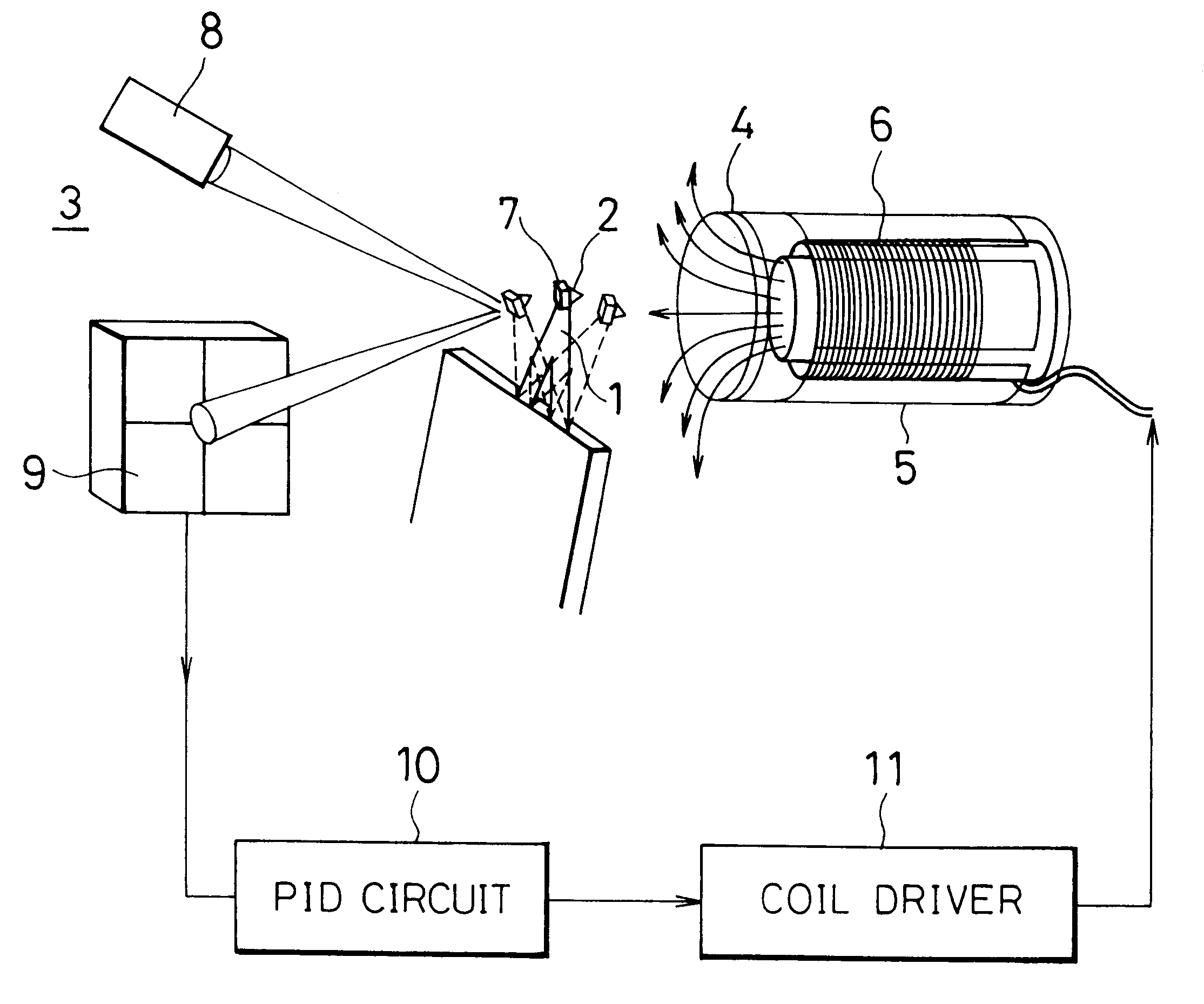
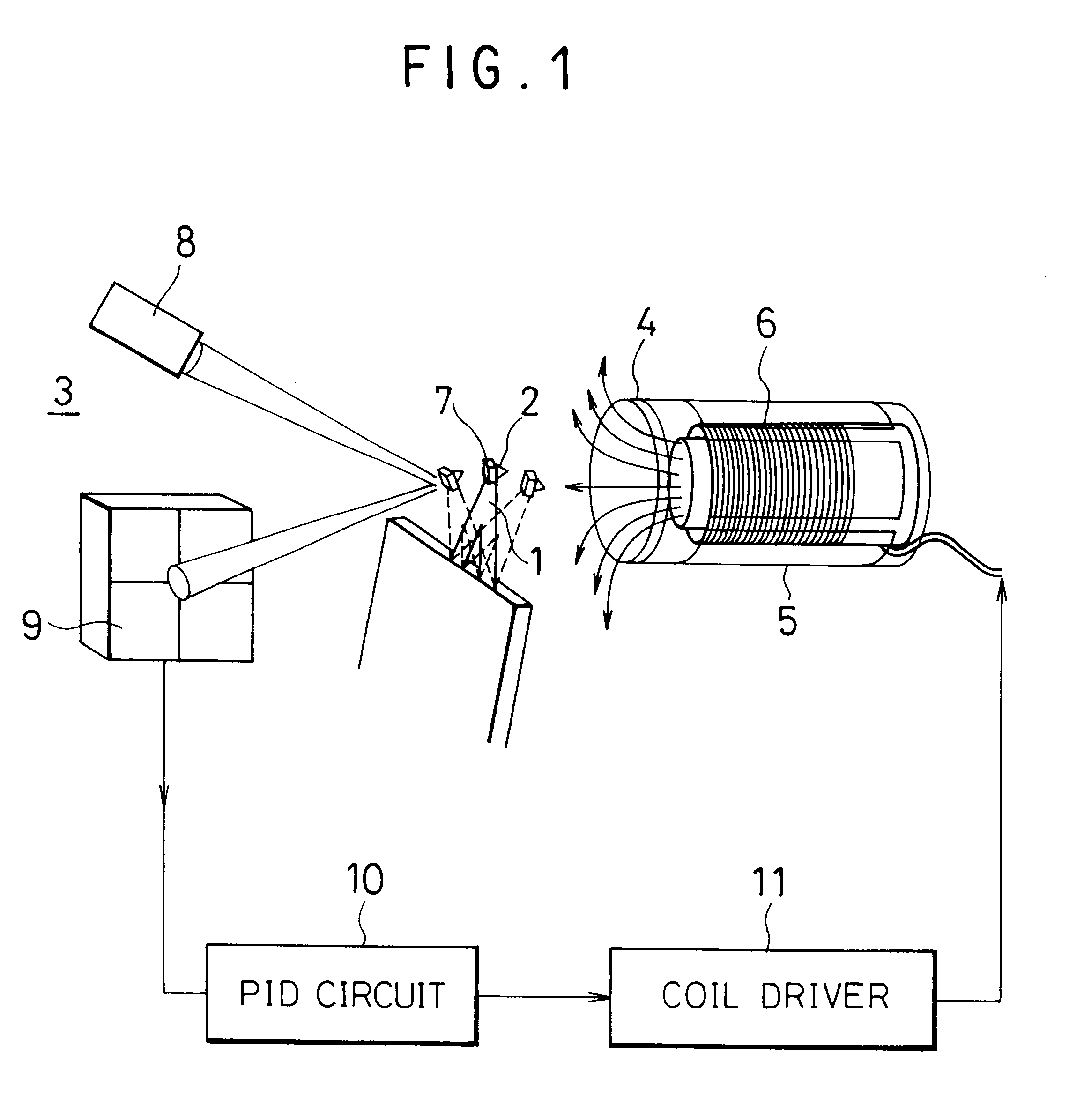
A method for controlling a force acting on a scanning probe according to the present invention will be described with reference to a scanning probe microscope shown in FIG. 1.

The scanning probe microscope comprises a cantilever 1 having a tip lower surface provided with a scanning probe 2, a detection unit 3 for detecting minute displacement of the cantilever 1 to output a displacement signal, a quartered photodiode 9 for converting the displacement signal into an electrical signal, a control signal generating circuit (PID circuit) 10 for processing the electrical signal for effective feedback, a position control unit 5 for controlling a position of a sample 4, a magnetic field control unit 6 for controlling a force acting on the scanning probe 2, and a driver 11 for driving the magnetic field control unit 6.

The magnetic field control unit 6 in this embodiment comprises a core and a coil wound about the core, is disposed inside a hollow portion of the position control unit 5, and ap...


PUM

PropertyMeasurementUnit
frequencyaaaaaaaaaa
frequencyaaaaaaaaaa
coil inductanceaaaaaaaaaa

Abstract

A method for controlling a force acting on a scanning probe of a cantilever by setting bandwidth of a feedback loop constituted by detecting minute displacement of the cantilever and controlling a force of the scanning probe to be greater than a primary resonant frequency of the cantilever.

Description

1. Field of the InventionThis invention relates to a method and apparatus for controlling a force acting on a scanning probe of a scanning probe microscope (SPM), particularly an atomic force microscope (AFM).2. Description of the Prior ArtMagnetically controlled SPMs have been noted in the literature for some time however one limitation to their widespread introduction is the deposition of magnetic material onto the force sensor. Prior art has included the glueing of small magnetic particles directly behind the tip and the deposition of thin magnetic films either on the back side or tip side of the force sensor. The problem with both the former methods is that it is time consuming, difficult and not reproduceable from sensor to sensor making any detailed calibration of force difficult. In the latter method the applied force tends to be much smaller, the reproducibility is still poor, the films often cause bending of the lever and have a tendency to peel in liquid.It has already bee...

Claims


Application Information

Patent Timeline
Patent Type & Authority Patents(United States)
IPC IPC(8): G12B21/20G12B21/00G12B21/08G12B21/02G01B21/30G01N37/00G01Q20/04G01Q30/20G01Q60/00G01Q60/24G01Q60/32G01Q60/38G01Q70/00
CPCB82Y35/00G01Q10/065G01Q60/38Y10S977/851Y10S977/865
Inventor JARVIS, SUZANNE PHILIPPALANTZ, MARK ALFREDDUERIG, URS
Owner IBM CORP
Why Eureka
Try Eureka