
Electric resistance measuring apparatus and method for circuit board

a technology of electric resistance and measuring apparatus, which is applied in the direction of resistance/reactance/impedence, individual semiconductor device testing, instruments, etc., can solve the problems of circuit board becoming unusable, unable to make higher yield of products afterward, and extremely difficult to achiev

Inactive Publication Date: 2001-10-02
ISC CO LTD
View PDF17 Cites 46 Cited by
  • Summary
  • Abstract
  • Description
  • Claims
  • Application Information

AI Technical Summary

Benefits of technology

The third object of the present invention is to provide an electric resistance measuring apparatus for circuit boards, which can perform expected measurement of electric resistance on electrodes to be inspected in a circuit board, even when the size of the electrodes is small, with high precision, and is easy to produce.
The fourth object of the present invention is to provide an electric resistance measuring apparatus for circuit boards, which can perform measurement of electric resistance on electrodes to be inspected with high precision without damaging such electrodes.
The fifth object of the present invention is to provide an electric resistance measuring method for circuit boards, which can perform expected measurement of electric resistance on electrodes to be inspected in a circuit board, even when the size of the electrodes is small, with high precision.
Since the layer connector member made of a conductive elastomer is brought into contact with the electrodes to be inspected, the electrodes to be inspected can be prevented from being damaged. In addition, the layer connector member comes into simultaneous contact with all the electrodes of the group consisting of a plurality of electrodes to be inspected, which are adjacent to each other, among the electrodes to be inspected in the circuit board to be inspected and is hence naturally greater in size than the individual electrodes to be inspected. Accordingly, the layer connector member can be easily formed, so that the electric resistance measuring apparatus can be produced with extreme ease.
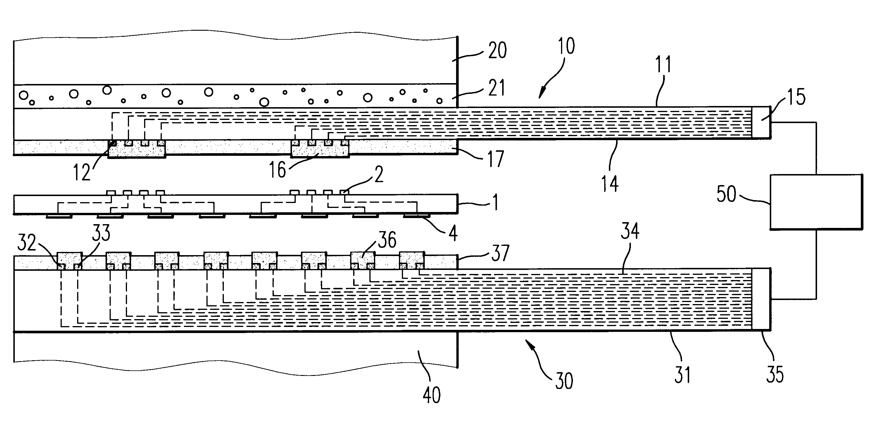
In the electric resistance measuring apparatus for circuit boards according to the second aspect, the adjacent front-side terminals in the connector member are electrically connected to each other by the short-circuit member arranged on the surface of the insulating base in the connector member, so that when a front-side terminal corresponding to a certain electrode to be inspected on one side of the circuit board to be inspected comes into contact with said electrode to be inspected, such an electrode to be inspected on said one side is simultaneously electrically connected to a plurality of the connecting electrodes through the connector member. Accordingly, one of the plurality of the electrodes to be inspected on said one side is specified, and 2 connecting electrodes are selected from among the plurality of the connecting electrodes electrically connected to the specified electrodes to be inspected on said one side to use one of them as an electrode for current supply and the other as an electrode for voltage measurement, whereby a voltage signal about the specified electrode to be inspected can be detected, so that the measurement of electric resistance as to the circuit board to be inspected can be performed with high precision.
Since the connecting electrodes and front-side terminals are in corresponding relation of one to one with the electrodes to be inspected on one side of the circuit board to be inspected, these electrodes are allowed to have a large size as substantially equal to the electrodes to be inspected. Accordingly, even when the size of the electrodes to be inspected on one side of the circuit board to be inspected is small, the connecting electrodes and front-side terminals can be formed with ease, so that the electric resistance measuring apparatus can be produced with extreme ease.

Problems solved by technology

In addition, since the probes are made of a metal, and their tips are in the form of a spire, the surfaces of the electrodes 91, 92 are damaged by pressing the respective probes against them, so that such a circuit board becomes unusable.
By such circumstances, the measurement of electric resistance cannot be performed on every circuit board as product, so that the measurement cannot but be conducted as the so-called sampling inspection, and the yield of the products cannot be made higher after all.
However, the above-described electric resistance measuring apparatus for circuit boards involves the following problems.
However, it is extremely difficult to do so, and after all, it is extremely difficult to produce an electric resistance measuring apparatus for circuit boards, which is suitable for use in measurement of electric resistance in a circuit board having small-sized electrodes at high density.
If the ratio is 1 or higher, a current flowing between the terminal electrode 32 for current supply and the terminal electrode 33 for voltage measurement through the elastic connecting member 36 becomes large, so that it may be difficult in some cases to measure electric resistance with high precision.
If this clearance is shorter than 10 .mu.m, a current flowing between the terminal electrode 32 for current supply and the terminal electrode 33 for voltage measurement through the elastic connecting member 36 becomes large, so that it may be difficult in some cases to measure electric resistance with high precision.
If this clearance is too long, it is difficult to suitably arrange both terminal electrodes to one of grid electrodes 4 corresponding to a small-sized dot electrode 2.
If the electric resistance is lower than 10 m.OMEGA., a current flowing between them becomes large, so that the measurement of the intended electric resistance cannot be performed with high precision.
However, it is actually necessary to use 2 electrodes, which satisfy, for example, specific conditions that the electric resistance value is 100 k.OMEGA. or lower, among connecting electrodes as the pair of measuring electrodes, otherwise it would be difficult to conduct measurement of the intended electric resistance because an measurement error becomes great.
However, the use of the inorganic filler in a great amount is not preferred because the orientation of the conductive magnetic particles by a magnetic field cannot be sufficiently achieved.

Method used


Image

  • Electric resistance measuring apparatus and method for circuit board
  • Electric resistance measuring apparatus and method for circuit board
  • Electric resistance measuring apparatus and method for circuit board

Examples


example a2

An electric resistance measuring apparatus was produced in the same manner as in Example A1 except that an upper-side adapter was produced under the following conditions in accordance with the construction illustrated in FIGS. 11 and 12.

[Inspection circuit board]

Dimensions of common connecting electrodes:

0.1 mm.times.1.5 mm

Clearance between common connecting electrodes:

0.22 mm

[Layer connector member]

Dimensions: 7 mm.times.7 mm; thickness: 0.2 mm

Conductive particles: material: nickel particles plated with gold on their surfaces; average particle diameter: 30 .mu.m; filling rate: 30% by volume

Elastic polymeric substance: silicone rubber

[Holding member]

Material: silicone rubber; thickness: 0.2 mm

Electric resistance between each dot electrode and its corresponding grid electrode in the same board to be inspected was measured in the same manner as in Example A1 except that in the electric resistance measuring apparatus described above, two of the common connecting electrodes were used as...

example b1

An electric resistance measuring apparatus for circuit boards was produced under the following conditions in accordance with the construction illustrated in FIG. 14.

(1) Upper-side adapter:

[Inspection circuit board]

Shape and dimensions of connecting electrodes:

circle, 0.1 mm in diameter

Clearance between connecting electrodes:

0.25 mm

[Connector member]

Thickness of insulating base: 200 .mu.m Thickness of short-circuit member: 50 .mu.m Projected height of front-side terminal: 30 .mu.m Outer diameter of conductor: 100 .mu.m Conductive particles: material: nickel particles plated with gold on their surfaces; average particle diameter: 30 .mu.m; filling rate: 30% by volume

Elastic polymeric substance: silicone rubber

Short-circuit member: a copper plate plated with nickel and gold in this order on its surface; thickness: 50 .mu.m

Electric resistance of conductor in the thickness-wise direction in a measurable state: 0.2 .OMEGA.

Electric resistance between adjacent front-side terminals: 0.02 .OM...

example b2

An electric resistance measuring apparatus for circuit boards was produced in the same manner as in Example B1 except that a connector member comprising a short-circuit member composed of a glass fiber reinforced epoxy resin sheet having a thickness of 50 .mu.m and a metal layer formed on the surface thereof, which was formed of copper and had a thickness of 8 .mu.m, was used in place of the connector member comprising the short-circuit member composed of a metal plate in accordance with the construction illustrated in FIG. 22, thereby measuring electric resistance between each dot electrode and its corresponding grid electrode in the same circuit board to be inspected. The result is shown in Table 2.


PUM


Abstract

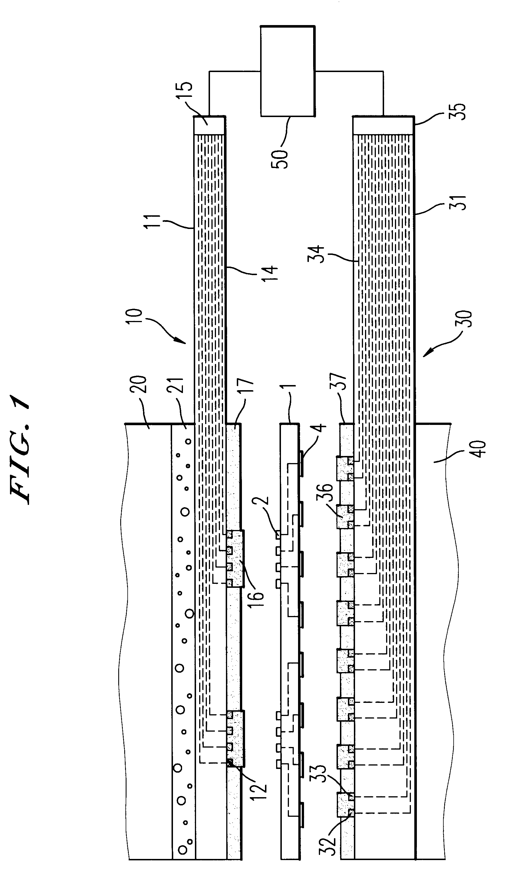
Provided are an electric resistance measuring apparatus for circuit boards, and an electric resistance measuring method using the same.An electric resistance measuring apparatus includes a one-side inspection circuit board having a plurality of connecting electrodes, and layer connector members provided on the inspection circuit board and formed of a conductive elastomer. Each of the layer connector members is brought into simultaneous contact with a plurality of connecting electrodes at one side thereof to be electrically connected thereto, and at the other side thereof, brought into simultaneous contact with a plurality of electrodes to be inspected to be electrically connected thereto. In this measurable state, two connecting electrodes are used for current supply and for voltage measurement, thereby performing measurement of electric resistance on a specified electrode to be inspected.Another electric resistance measuring apparatus includes a connector member provided on the surface of the inspection circuit board. The connector member is composed of an insulating base, front-side terminals, back-side terminals and a short-circuit member for electrically connecting the adjacent front-side terminals to each other.

Description

1. Field of the InventionThe present invention relates to electric resistance measuring apparatus and methods for circuit boards.2. Description of the Background ArtIn the electrical inspection of circuit boards, it is generally conducted to measure electric resistance between electrodes in the circuit boards.In the measurement of such electric resistance, there has heretofore been adopted means for finding the value of electric resistance between electrodes 91, 92 to be inspected, which are electrically connected to each other in a circuit board 90 to be inspected, for example, as illustrated in FIG. 28, in which probes PA, PD for current supply and probes PB, PC for voltage measurement are pressed against and contacted with the respective electrodes 91, 92, respectively, a current is supplied between the probes PA, PD for current supply from an electric power unit 93 in this state, and a voltage signal detected by the probes PB, PC for voltage measurement at this time is processed...

Claims


Application Information

Patent Timeline
Patent Type & Authority Patents(United States)
IPC IPC(8): G01R31/28G01R27/02G01R31/02G01R1/073
CPCG01R31/2812
Inventor SHIMODA, SUGIROKIMURA, KIYOSHI
Owner ISC CO LTD
Learn More