Surface-mounted antenna and communication apparatus using same

a technology of communication apparatus and antenna, applied in the structure of individual energized antenna arrays, resonant antennas, radiating elements, etc., can solve the problems of signal interference between radiation electrodes, inability to meet the demands of high performance and miniaturization, and difficulty in achieving the wide frequency bandwidth of antennas

Inactive Publication Date: 2001-10-02
MURATA MFG CO LTD
View PDF3 Cites 16 Cited by
  • Summary
  • Abstract
  • Description
  • Claims
  • Application Information

AI Technical Summary

Problems solved by technology

Although various antenna structures have been designed and provided, no antenna can sufficiently satisfy the demands for both high performance and miniaturization.
However, when the pair of radiation electrodes is disposed with a narrow distance therebetween without considering the structure in which the electrodes are disposed, signal interference occurs between the radiation electrodes.
This creates a critical problem in that it is difficult for the antenna to have a wide frequency bandwidth.
Howev...

Method used


Image

  • Surface-mounted antenna and communication apparatus using same
  • Surface-mounted antenna and communication apparatus using same
  • Surface-mounted antenna and communication apparatus using same

Examples


first embodiment

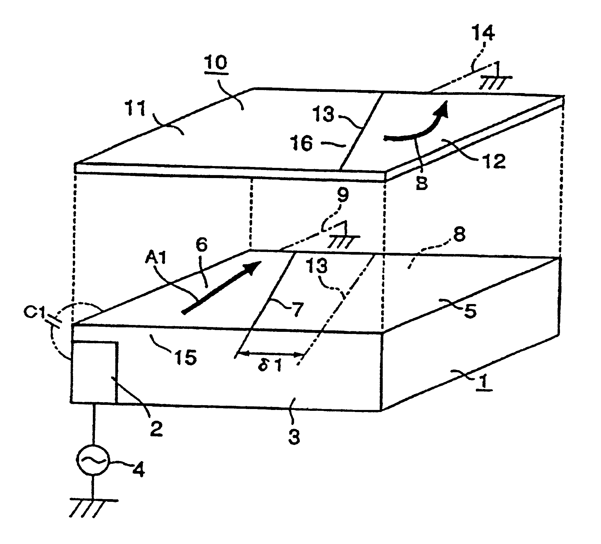
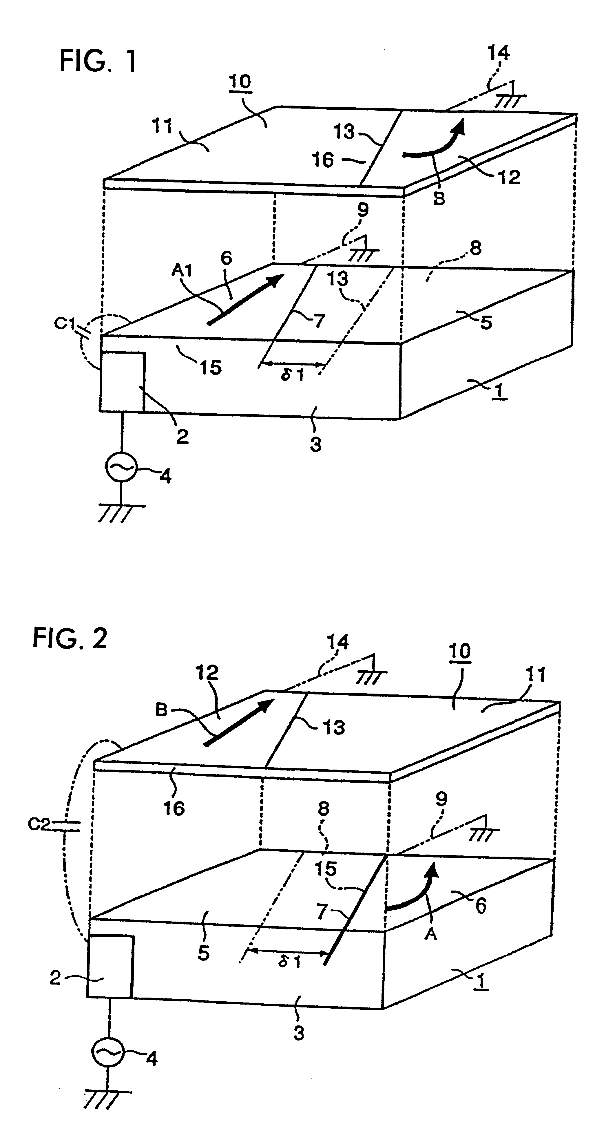
FIG. 1 shows the structure of the main part of a surface-mounted antenna according to the present invention. In this figure, a base dielectric substrate 1 is formed of a material having a high permittivity such as ceramic or resin, and has a rectangular (rectangular parallelepiped) configuration. On the bottom of the base dielectric substrate 1, a grounding electrode (not shown) having a wide area and a feeding connection electrode 2 insulated from the grounding electrode are disposed. The feeding connection electrode 2 extends from the bottom of the base dielectric substrate 1 to the front surface 3 thereof. The feeding connection electrode 2 is connected to a signal source 4.

The upper surface of the base dielectric substrate 1 is denoted by reference numeral 5. A trapezoidal first radiation electrode 6 is formed of a conductive material in the left-half region of the upper surface 5 of the base dielectric substrate 1. An edge 7 of the trapezoidal electrode 6 comprises an oblique l...

third embodiment

In the third embodiment, a feeding signal supplied from a signal source 4 is supplied to the first radiation electrode 6 of the base dielectric substrate 1 via the capacitance C1, and then is supplied to the second radiation electrode 12 of the base dielectric substrate 1 via the capacitance of the gap .delta.1. Meanwhile, the feeding signal from the first radiation electrode 6 of the base dielectric substrate 1 is supplied to the first radiation electrodes 6 of the multi-layer dielectric substrate 10 via the capacitance C3, and then, is supplied from the first radiation electrode 6 of the multi-layer dielectric substrate 10 to the second radiation electrode 12 thereof via the capacitance of the gap .delta.2.

In each of the first and second radiation electrodes 6 and 12 of the base dielectric substrate 1 and the multi-layer dielectric substrate 10, a current flows from the short edges (conducting electrodes 9 and 14) to open ends 15 and 13. Then, the first radiation electrode 6 of th...

fifth embodiment

Similar to the other embodiments, in the fifth embodiment, by adjusting the gaps .delta.1, .delta.2, and .delta.3 between the radiation electrodes of the individual layers and the gaps angles .theta. as needed, directions in which the radiation electrodes of the individual layers vertically adjacent excite can be adjusted in different directions, that is, in non-parallel directions. In addition, by selectively changing the permittivity of each of the multi-layer dielectric substrates 10a and 10b, isolation between the vertically adjacent upper and lower layers can be adjusted.

Furthermore, in this embodiment, by setting the permittivity of each of the multi-layer dielectric substrates 10a and 10b to be higher than the permittivity of the base dielectric substrate 1, electric fields are concentrated on the multi-layer dielectric substrates 10a and 10b so that the band of a set frequency can be widened. Particularly, by maximizing the permittivity of the top multi-layer dielectric subs...


PUM


Abstract

A compact surface-mounted antenna having a wide frequency band. In the surface-mounted antenna, a first radiation electrode is formed on the left-half region of the upper surface of a base dielectric substrate. A multi-layer dielectric substrate is laminated on the upper surface of the base dielectric substrate to be bonded and fixed thereto. A second radiation electrode is formed on the right-half region of the upper surface of the multi-layer dielectric substrate. The first and second radiation electrodes are not vertically opposed to each other. Opposing edges of the first and second radiation electrodes are oblique lines. A feeding signal of a signal source is supplied to the first radiation electrode by coupling from a feeding connection electrode, and then, is supplied to the second radiation electrode from the first radiation electrode by another coupling between the first and second radiation electrodes. A direction in which the first radiation electrode excites is set to be substantially perpendicular to a direction in which the second radiation electrode excites.

Description

1. Field of the InventionThe present invention relates to surface-mounted antennas and communication apparatus using the same, such as cellular phones.2. Description of the Related ArtWith the recent expanding proliferation of cellular phones, the technological development race is heating up with the aims of miniaturization and high performance of the cellular phones. In order to accomplish there aims, it is essential to reduce the sizes of antennas incorporated in the cellular phones while improving the performance of the antennas.Although various antenna structures have been designed and provided, no antenna can sufficiently satisfy the demands for both high performance and miniaturization. This type of antenna is yet to appear on the market.As a promising compact and highly efficient antenna the present inventors have focused much attention on a surface-mounted antenna. The surface-mounted antenna, for example, can be made by disposing a pair of electrodes close to each other on ...

Claims


Application Information

Patent Timeline
IPC IPC(8): H01Q1/24H01Q5/00H01Q9/04H01Q1/38H01Q21/06H01Q13/08
CPCH01Q1/243H01Q1/38H01Q9/0414H01Q5/385H01Q9/0457H01Q5/378H01Q9/0421
Inventor TSUBAKI, NOBUHITONAGUMO, SHOJIKAWAHATA, KAZUNARI
Owner MURATA MFG CO LTD
Why Eureka
Try Eureka