
Fault protection device

A fault protection and failure technology, applied in emergency protection circuit devices, circuit devices, battery circuit devices, etc., can solve problems such as unmanufacturable, limited electrolyte decomposition voltage, high price-to-energy ratio, etc.

Inactive Publication Date: 2010-02-24
LITE ON TECH CORP
View PDF0 Cites 0 Cited by
  • Summary
  • Abstract
  • Description
  • Claims
  • Application Information

AI Technical Summary

Problems solved by technology

However, supercapacitors have chemical properties due to their chemical materials, and are prone to leakage. In addition, due to the fast discharge rate due to some physical properties, they will soon run out of power under the aforementioned two factors, and Limited by the decomposition voltage of the electrolyte (aqueous electrolyte 1V, organic electrolyte about 2.5V), its withstand voltage is low, coupled with the cost of electrode materials, supercapacitors have a higher price-to-energy ratio than other capacitors and batteries
[0006] The technology of general energy storage components cannot achieve the advantages of long life (high charge and discharge times), high energy storage density, instantaneous high power output, fast charge and discharge, etc., and the current secondary batteries and supercapacitors require electrolyte Storing electrical energy in a chemical way cannot be manufactured under the general current semiconductor manufacturing process, so once the packaging is completed, the capacity of storing electrical energy is not easy to change, and the peripheral related circuits are less flexible in planning, so the existing technology There is still room for improvement
[0007] It can be seen that the above-mentioned existing energy storage elements obviously still have inconvenience and defects in structure and use, and need to be further improved urgently.
In order to solve the above-mentioned problems, the relevant manufacturers have tried their best to find a solution, but for a long time no suitable design has been developed, and the general products do not have a suitable structure to solve the above-mentioned problems. Urgent problem

Method used


Image

  • Fault protection device
  • Fault protection device
  • Fault protection device

Examples


Embodiment Construction

[0042] In order to further explain the technical means and effects of the present invention to achieve the intended purpose of the invention, the specific implementation, structure, characteristics and effects of the fault protection device proposed according to the present invention will be described below in conjunction with the accompanying drawings and preferred embodiments. Details are as follows.

[0043] first preferred embodiment

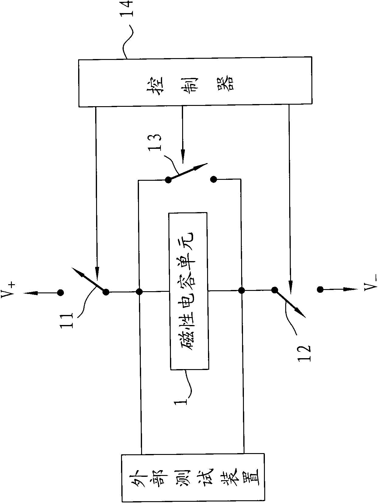
[0044] see figure 1 Shown is a schematic circuit diagram of the fault protection device of the present invention. The fault protection device of the present invention includes: a magnetic capacitance unit 1, a first working switch 11, a second working switch 12, an isolating switch 13 and a controller 14; and it is worth noting that these switches 11-13 The names of these three switches do not limit the types of these three switches or limit these three switches to be different types of switches. On the contrary, these three switches 11-...


PUM


Abstract

The invention discloses a fault protection device, which comprises a magnetic capacitor unit and an isolating switch, wherein the magnetic capacitor unit is used for storing electric energy and is provided with a first end and a second end; the isolating switch can electrically connect the first end of the magnetic capacitor unit and the second end of the magnetic capacitor unit in a switching way; and when the magnetic capacitor unit has a fault in a working mode, the isolating unit is turned on to form a short-circuit path between the first end and the second end of the magnetic capacitor unit to isolate the failed magnetic capacitor unit. The fault protection device can realize an energy storage element which is programmable and has the advantages of long service life, high energy-storage density, instantaneous high power output, quick charge and discharge and the like. The fault protection device is suitable to be used when a magnetic capacitor has a fault, and has the functions ofisolating the failed magnetic capacitor to protect other circuit elements.

Description

technical field [0001] The invention relates to a fault protection device, in particular to a fault protection device which can isolate the faulty magnetic capacitor to protect other circuit components when a magnetic capacitor fails. Background technique [0002] Nowadays, energy storage components are widely used in home appliances, handheld devices, such as mobile phones (Mobile Phone), personal digital assistants (Personal Digital Assistant, PDA), vehicles and other products to meet people's demand for independent energy systems . Energy storage components in a narrow sense mainly refer to batteries, including primary batteries and secondary battery products; while energy storage components in a broad sense refer to all components with energy storage functions, including capacitors and inductors for temporary energy storage, and a The super capacitor (Super capacitor) between the battery and the capacitor is also included. [0003] Capacitors store energy in the form o...

Claims


Application Information

Patent Timeline
Patent Type & Authority Applications(China)
IPC IPC(8): H02J15/00H02H7/20
CPCH02H7/16H02J7/345
Inventor 郑青峯周锦城
Owner LITE ON TECH CORP
Learn More