Electrophotochromic smart windows and methods

a technology of photochromic and smart windows, applied in the direction of door/window protective devices, instruments, constructions, etc., can solve the problems of inability to make satisfactory electro-optical modulating materials for smart windows, partial and/or excessively slow, and the difficulty of complex pec devices having the necessary clarity, etc., to achieve the effect of improving the switching time of ec cells and less risk of damage to the cells

Inactive Publication Date: 2001-10-02
DYESOL LTD
View PDF17 Cites 114 Cited by
  • Summary
  • Abstract
  • Description
  • Claims
  • Application Information

AI Technical Summary

Benefits of technology

It is also desirable, but not essential, to provide a PEG smart window incorporating electronic control means that allows improved EC cell switching times with less risk of d...

Problems solved by technology

This is most difficult to achieve with complex PEC devices having the necessary clarity, whether darkened or bleached.
Further, the PE and EC elements of a PEG window are inherently mismatched so that darkening tends to be non-uniform, partial and/or excessively slow.
However, a liquid crystal layer does not make a satisfactory electro-optical modulating material for a smart window as clarity is poor, particularly when the window is darkened.
Also, since the PE cells and the voltage regulator must be installed separately from the window, the mounting and connection of this smart window will be expensive and unsightly.
Although the device is essentially self-contained, the various layers required for the EC device and the PE cells are deposited under vacuum using masks by conventional PVD (physical vapour deposition), sputtering or CVD (chemical vapour deposition) techniques, severely limiting the area of window and making the device expensive.
Also, the electrical arrangement necessitates the use of the same voltage for bleaching as for darkening which either results in excessively slow switching times or damage to the EC cell.
Finally, the area of the window available to the PE cells is small so the power output from them is also small; moreover, the PE cells are unsightly.
Again, since the PE cells and the voltage regulator must be installed separately from the window, the mounting and connection of this smart window will be expensive and unsightly Also, electrical control of the window will not be satisfactory since the threshold voltage of silicon PE cells (acting as diodes) is a substantial proportion of the voltage needed to bleach the window.
As about eight thin layers of transparent materials, including t...

Method used


Image

  • Electrophotochromic smart windows and methods
  • Electrophotochromic smart windows and methods
  • Electrophotochromic smart windows and methods

Examples


Embodiment Construction

Having broadly portrayed the nature of the present invention, examples of PEC smart windows and their control means will now be described by way of illustration. In the following description, reference wilt be made to the accompanying drawings in which:

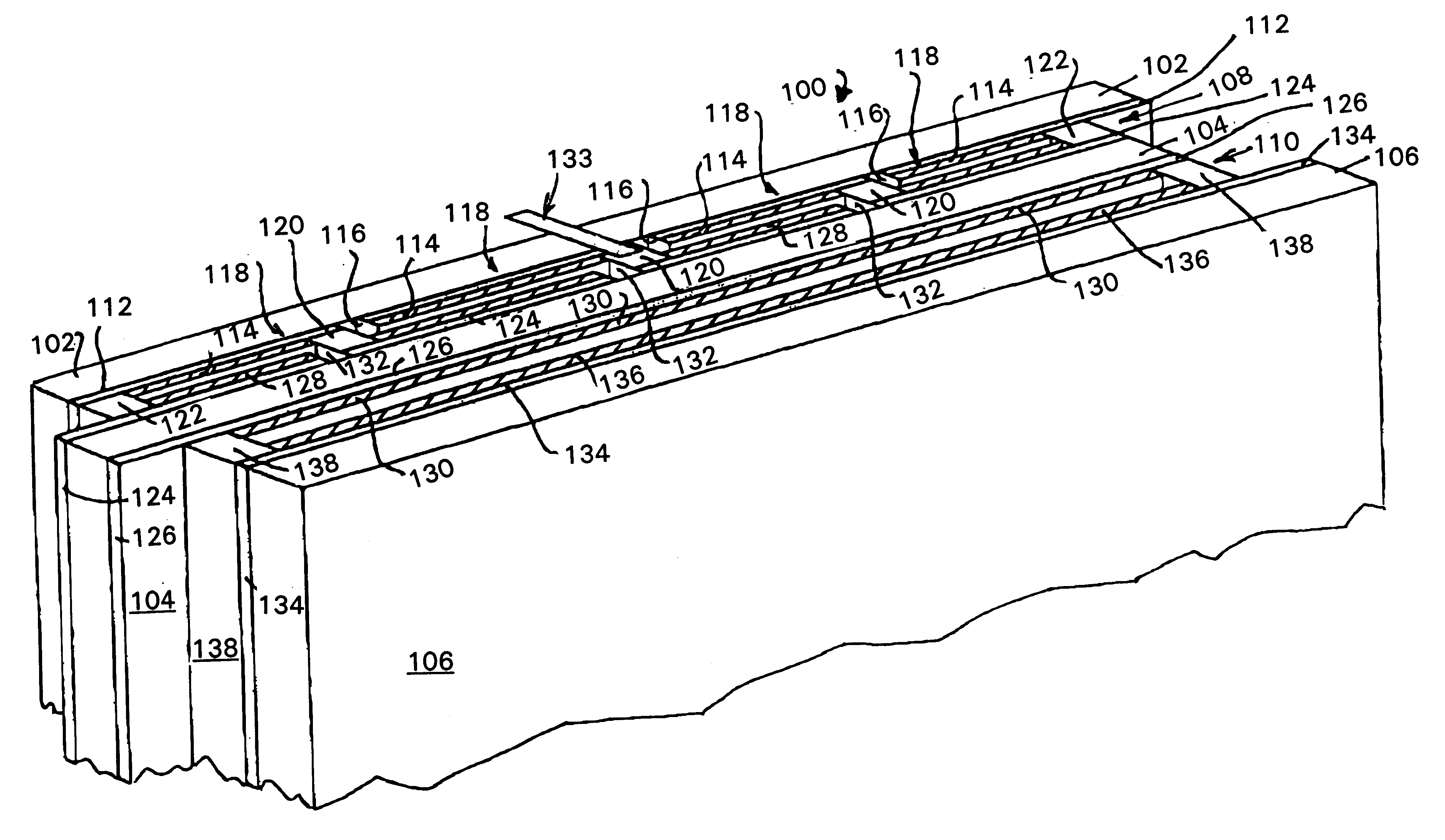
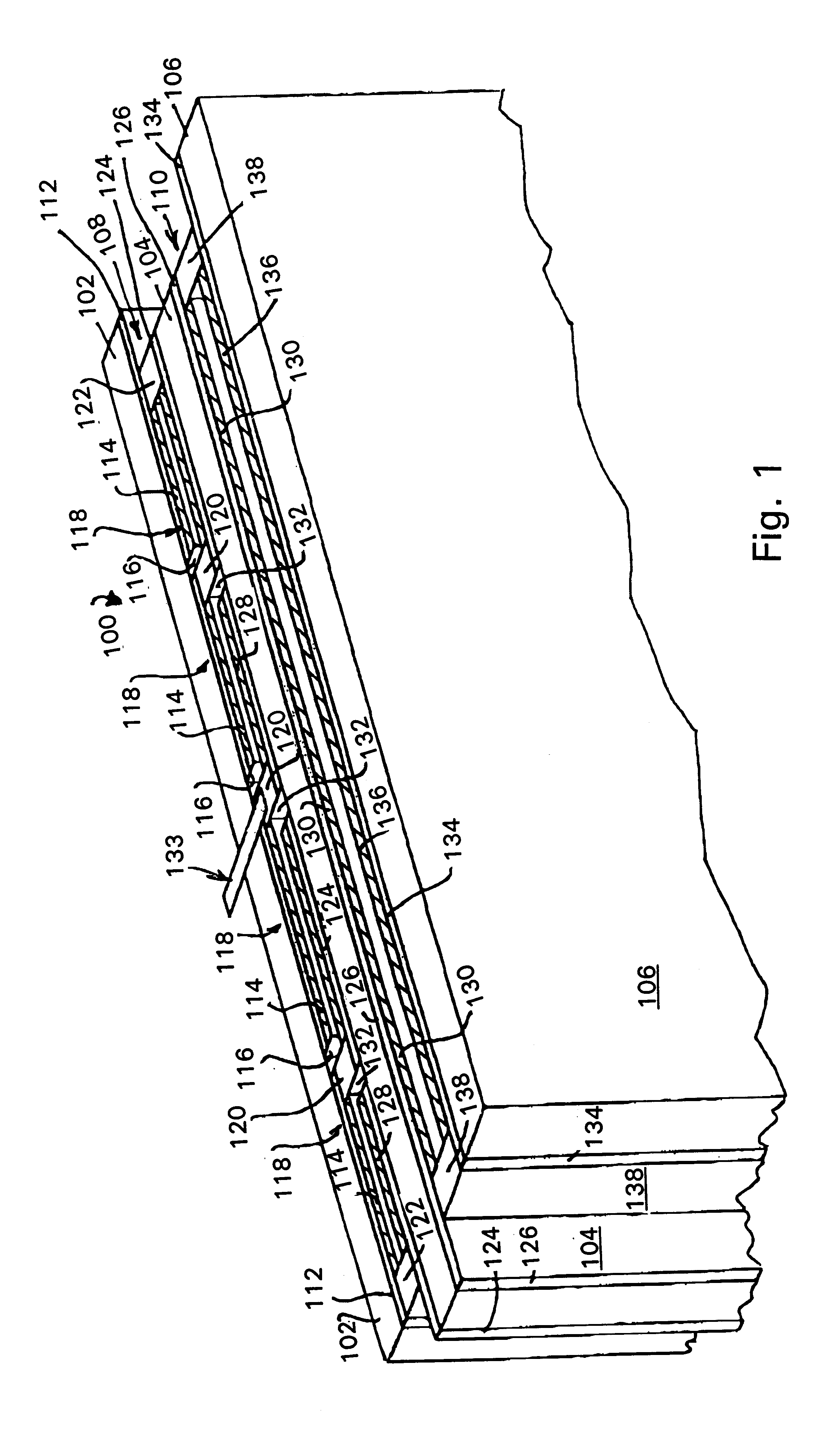
FIG. 1 is a perspective view (not to scale) from above of the top edge of an unsealed and unframed three-pane PEC smart window which forms the first example of the present invention.

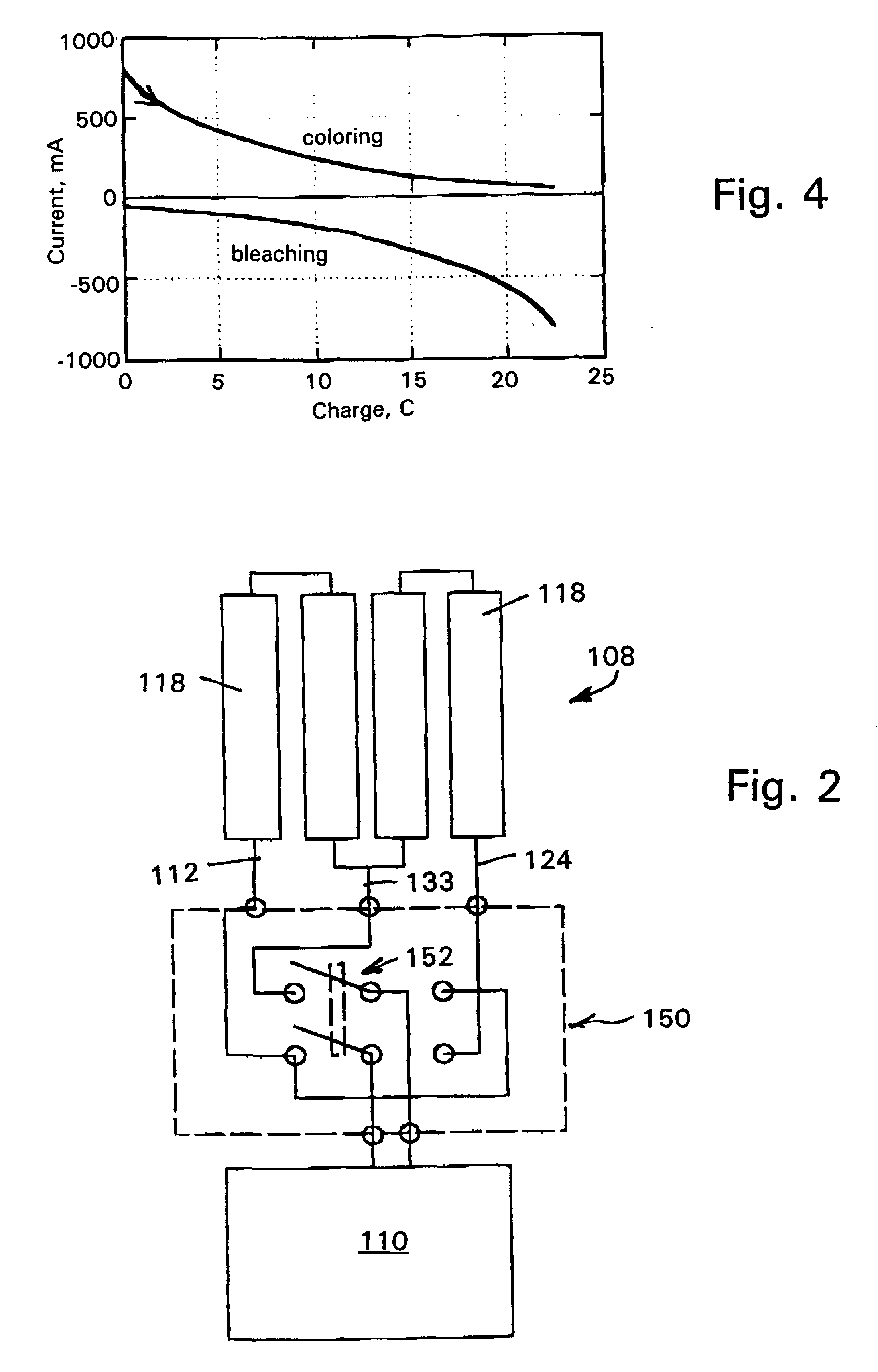
FIG. 2 is a block diagram of an example of a simple switch-based control means suitable for use with the window of FIG. 1.

FIG. 3 is a block diagram of an example of a microprocessor-based control means suitable for use with the window of FIG. 1

FIG. 4 is a graph illustrating typical safe charging and discharging profiles for the EC cell of the PEC window of FIG. 1.

FIG. 5 is a diagrammatic sectional elevation of a two-pane smart window that forms the second example of a smart window formed in accordance with the present invention.

The chosen example of a smar...


PUM


Abstract

A smart window comprising a regenerative photolectrochomic (RPEC) photovoltaic element (108) juxtaposed with an electrochromic (EC) element (110). Microprocessor-based control mechanism (200) connecting the RPEC element to the EC element for controlling the current delivered to and from the EC element. The controller (200) including look-up tables (204 and 206) for determining the safe current to or from the EC element having regard to the amount of charge to be delivered or removed and the charge status of the EC element, the determination of charge status, charge still required and current to be delivered being made frequently to ensure that the current is kept within safe limits while minimizing switching times. New smart windows are also disclosed.

Description

This invention relates to smart windows suitable for use in the glazing of buildings. The smart windows concerned are those which have (i) electrochromic (EC) elements that can be darkened (ie, made to be more coloured or less transparent) or bleached (ie, made to be less dark or more transparent) by the addition or extraction of electric charge, and (ii) photoelectric (PE) elements which can supply the electric charge needed to effect the darkening of the EC elements when the window is exposed to sunlight. Such combined PE-EC devices are sometimes called `photoelectrochromic` (PEC) devices.The preferred PE elements for use in the PEC smart windows of this invention are those of the dye-sensitised regenerative photoelectrochemical (RPEC) type wherein photons striking a solid semiconductor photoelectrode produce charge carriers that are separated at a junction between the electrode and a liquid electrolyte, when the photoelectrode and the electrolyte are connected by an external elec...

Claims


Application Information

Patent Timeline
IPC IPC(8): E06B9/24G02F1/01G02F1/163G02F1/153
CPCE06B9/24G02F1/163E06B2009/2464
Inventor TULLOCH, GAVIN EDMUNDSKRYABIN, IGOR LVOVICH
Owner DYESOL LTD
Why Eureka
Try Eureka