
Suspension arm

a suspension arm and arm technology, applied in the direction of suspension arms with a strong grip, suspension components, vehicle components, etc., can solve the problems of increasing the working man-hour and manufacturing cost, requiring special high dimensional accuracy, and requiring further lightening of the suspension arm

Inactive Publication Date: 2001-11-06
SHOWA DENKO KK +1
View PDF7 Cites 28 Cited by
  • Summary
  • Abstract
  • Description
  • Claims
  • Application Information

AI Technical Summary

Benefits of technology

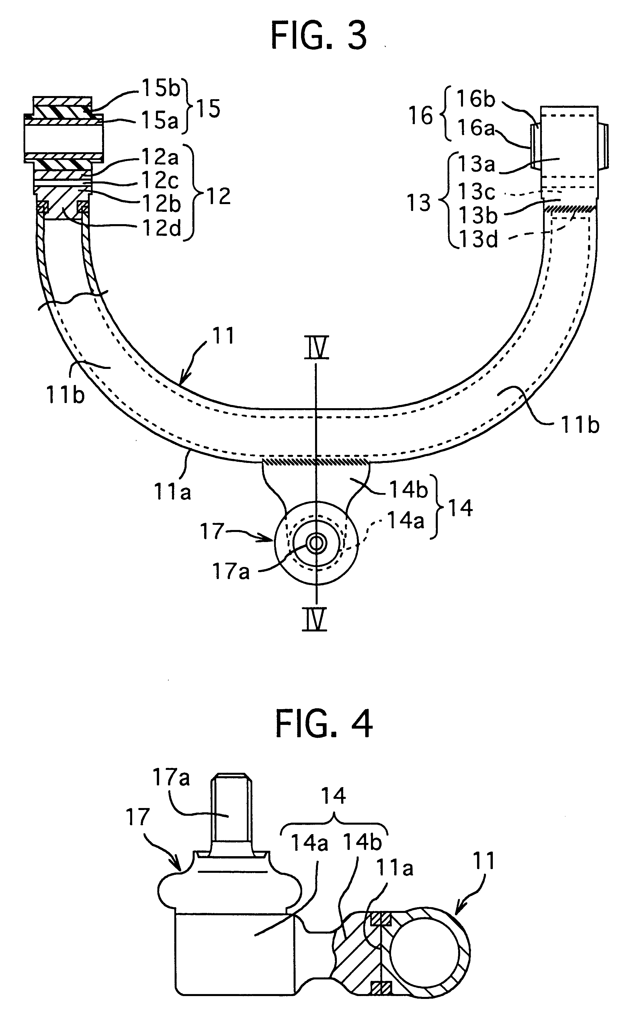
The arm member of this invention has at least a part thereof, a bent portion bent into the arch shape. This bent portion can be formed over the arm member such as a semi-circle or quater circle, or can be locally formed at a central portion of the arm member such as U-shape or V-shape. This bent portion is formed by bending the arm member by a known pressing apparatus easily, after the bearing members are attached to the both end of the arm member. As a result, the bearing members can be attached to the straight arm member easily.
In the invention recited in the claim 3, the arm member has a flat surface formed at a part of an outer peripheral surface thereof in extruding and extending in the extruded direction. According to this invention, when the intermediate bearing member is joined to the arm member, the joined surface of the arm member is flat, not curved, at least in a cross-section perpendicular to the extruding direction, which can heighten the joining responsibility of the intermediate bearing member to the arm member. In addition, when the arm member is formed into the pipe shape which has an inner peripheral surface, due to formation of the flat surface at the part thereof, a modulus of section and a rigidity of the arm member can be increased, to thereby heighten the strength and durability of the arm member.
In the invention recited in the claims 4 to 6, the both end portions of the arm member, or the both bearing member at the both ends of the arm member are connected with each other by a connecting bar. According to this invention, a positional error occurred between the both ends of the arm member in bending the arm member can be corrected or absorbed when the connecting bar is attached between the both ends of the arm member or between the both bearing members. Thus, the dimensional accuracy of the shaft to shaft distance between the both bearing members attached to the both ends of the bent arm member can be increased. The connecting bar can be formed by a rigid body such as a metal, but is preferably formed by the aluminium alloy, in view of the material (aluminium alloy) of the arm member and the bearing members to which the connecting bar is connected, and lightening of the suspension arm including the connecting bar.
In the invention recited in the claim 7, the intermediate bearing member is joined to the flat surface of the arm member, which heighten the joining strength of the intermediate bearing member to the arm member. In the invention recited in the claim 6, the arm member has the semi-circular or quater circular shape, which can absorb the vivrations in various direction between the both ends and the intermediate portion of the arm member.
In the invention recited in the claims 9 and 10, a connecting members with vibration preventing fuction are attached to the bearing members at the both end of the arm member, or the intermediate bearing. According to this invention, on account of the connecting member with vibratio preventing function attached to the both bearing members or the intermediate bearing memer, the suspension arm can be connected to an another suspension arm or an attaching member easily. The connecting members with vibration preventing fuction are attached to the both bearing members or the intermediate bearing memer to connect this connecting member with another or adjacent connecting members with vibration preventing fuction. As the connecting member with vibration prevent, a vibration preventing bushing provided with a rubber elastic body for absorbing the vibration, or a ball joint provided with a joint shaft which has a cubic portion held contactingly slidably by a spherical contact with a mating member and which slides to change an axis of the joint shaft far absorbing the vibration can be used.
According to this invention, the arm member of the aluminium alloy can be formed by the pipe member of the hollow construction, so that the amount of the aluminium alloy material can be greatly decreased to lighten the suspension arm, and the rigidity is maintained. Also, no additional working for accurately positioning the paired bearing at the both ends of the arm member is necessary.

Problems solved by technology

However, when these bent suspension are formed by forging the aluminium alloy, the suspension arm of hollow shape is hardly formed, which makes further lightening of the suspension arm difficult.
In addition, when the suspension is comprised of an arm member and a pair of bearing members attached to both ends of the arm member, if whole of the suspension arm including the bearings are formed by the forging, a bearing to bearing distance between the bearing members provided at the both ends of the arm member requiring an especially high dimensional accuracy, can not be maintained in high accuracy.
As a result, various cutting working become necessary after the forging for maintaining the dimensional accuracy, which introduces increase of a working man-hour and a manufacturing cost.

Method used


Image

  • Suspension arm
  • Suspension arm
  • Suspension arm

Examples


Embodiment Construction

Hereinafter, preferred embodiments of the present inventions will be explained with reference to attached drawings. However, it is noted that the present invention is not limited to these embodiments, but can include various variation or modification within spirit thereof.

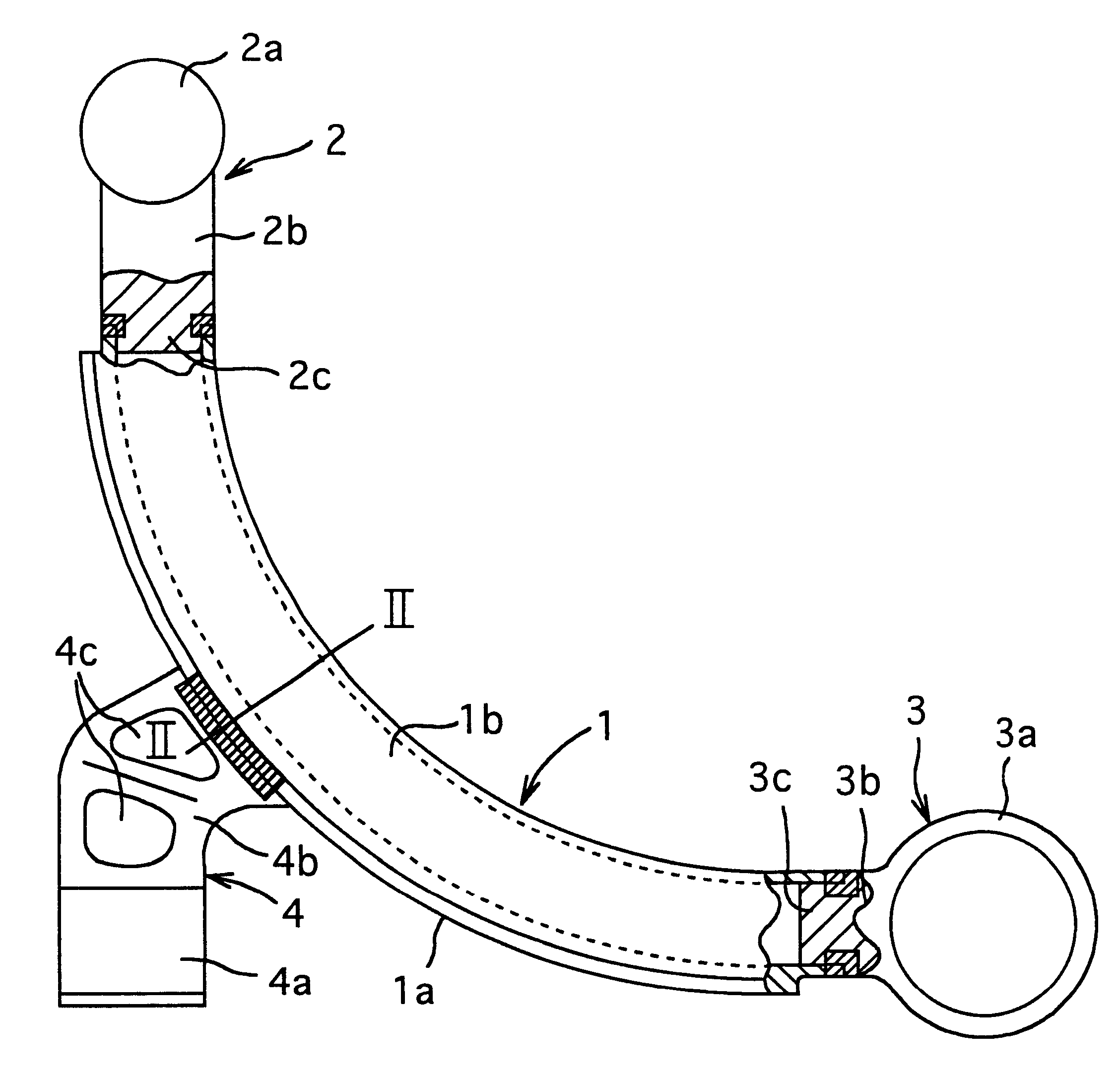
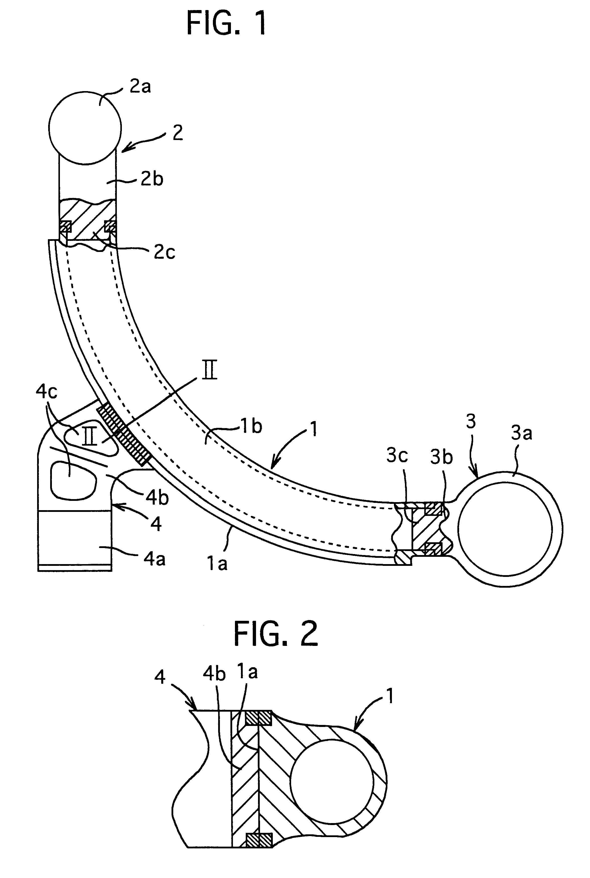
FIG. 1 is a plan view (partially broken) of the suspension arm according to a first embodiment of the present invention, and FIG. 2 is across-section along a line II--II in FIG. 1.

A suspension arm of this embodiment is comprised of, as shown in FIG. 1, an arm member 1 made of an aluminium alloy and formed into a pipe-shape by an extrud and bent into an arch-shape (quater circle), a first bearing member 2 made of an aluminium alloy and joined to one end of the arm member 1, a second bearing member 3 made of an aluminium alloy and joined to another end of the arm member 1, and an intermediate bearing member 4 joined to an intermediate portion of the arm member 1.

The arm member 1 is manufactured by extruding the alumi...


PUM


Abstract

This invention relates to a suspension arm comprised of a bent arm member, and a pair of bearing members joined to end portion thereof. The arm member of the conventional suspension is made of the aluminium alloy and manufactured by the forging. So, the arm member of hollow construction and has a bent portion is hardly manufactured by the forging. In view of this, in the present invention, the arm member 1 made of the aluminium alloy and has hollow construction is manufactured by the extrusion, and bent before a pair of bearing members 2,3 are joined to each of end portions.

Description

1. Field of the InventionThis invention relates to a suspension arm used in a suspension mechanism mounted on a vehicle.2. Related ArtConventionally, in a suspension mechanism mounted on a vehicle, a suspension arm connected with an another connecting bar in a vibration preventing condition and forms a link mechanism has been used. This suspension arm is manufactured by or made of mainly a ferrous material and formed by a press working or a forging. Recently, for lightening the suspension arm, a light metallic materials such as an aluminium alloy and the like formed by the forging have been adopted.By the way, the suspension arm can have various shapes corresponding to an attached location thereof to the vehicle. For example, an upper arm attached to an upper portion of the suspension mechanism and a lower arm attached to a lower portion of the suspension arm have bent shapes such as an arch shape, V-shape or U-shape. However, when these bent suspension are formed by forging the alu...

Claims


Application Information

Patent Timeline
IPC IPC(8): B60G7/00
CPCB60G7/001B60G2204/41B60G2204/416B60G2206/012B60G2206/122B60G2206/124B60G2206/7102B60G2206/8103B60G2206/8105B60G2206/8201
Inventor KATO, RENTAROTOCHIGI, MASAHARUKAWATA, NAOYUKINISHIKAWA, NAOKI
Owner SHOWA DENKO KK
Learn More