Magnetic resonance imaging head coil

a magnetic resonance imaging and head coil technology, applied in the field of magnetic resonance imaging systems, can solve the problems of homogeneity and imaging quality, adversely affecting imaging quality, and attempts to shorten the rf head coil have not been entirely satisfactory, so as to improve quality imaging and improve homogeneity in the magnetic field.

Inactive Publication Date: 2001-11-06
GENERAL ELECTRIC CO
View PDF7 Cites 33 Cited by
  • Summary
  • Abstract
  • Description
  • Claims
  • Application Information

AI Technical Summary

Benefits of technology

An asymmetrical coil assembly may surround the first cylinder and extend to the tapered portion of the conductors. The coil in the central region of the asymmetrical coil assembly is of a larger diameter than the end coils of the coil assembly. The resultant improved homogeneity in the magnetic field provides improved quality imaging. The head coil may be pulsed by the transmit coil of the magnetic resonance imager or alternatively may act as a receiver coil for transmit pulses from the transmit coil surrounding the interior of the bore of the superconducting magnet.

Problems solved by technology

Pulsing current through conductors generate pulsing magnetic fields external to the conductors which can interfere with other magnetic fields in the superconducting magnet including the homogeneity of the main magnetic field in the imaging volume, and adversely affect imaging quality.
Attempts to shorten the RF head coil have not proven entirely satisfactory, providing for example hot spots or areas of high B1 amplitude which disrupt the RF magnetic field homogeneity and the imaging quality.

Method used


Image

  • Magnetic resonance imaging head coil
  • Magnetic resonance imaging head coil
  • Magnetic resonance imaging head coil

Examples


Embodiment Construction

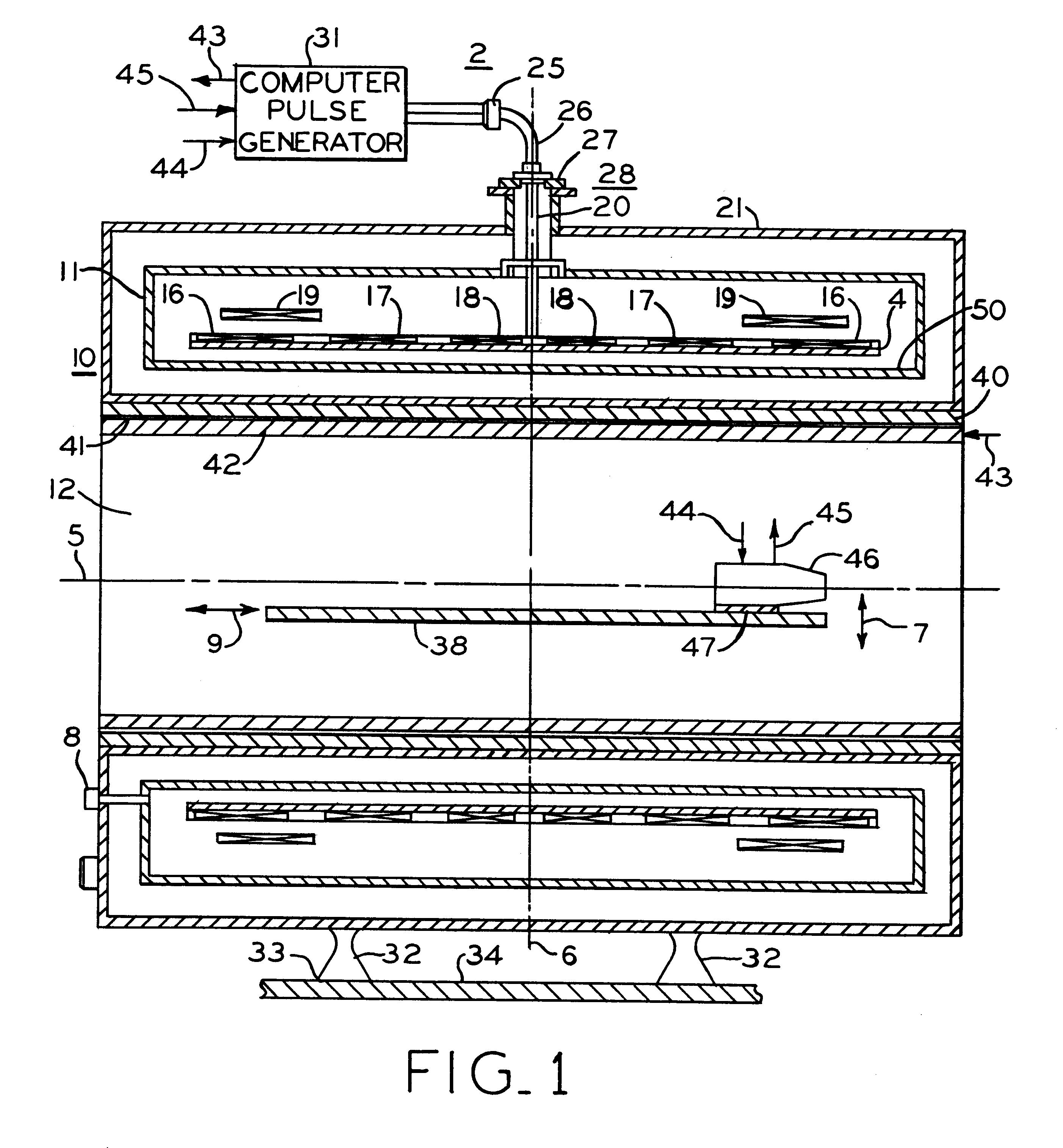
Referring first to FIG. 1, MRI superconducting magnet assembly 10 includes cryogen pressure vessel 11 positioned concentrically within vacuum vessel 21 and forming central imaging bore 12 about axis 5. Positioned within pressure vessel 11 is composite drum 4 with axially spaced main magnet coils 16 wound in axial slots on the drum. Correction coils 17. 18 and 19 within pressure vessel 11 enable shimming of the magnetic field in bore 12 to improve magnetic field homogeneity to acceptable limits. Supports 32 secure superconducting magnet assembly 10 on floor 34.

External electrical power and control connections are provided through access port 28 by lead assembly 26 which includes connector 25 outside vacuum vessel 23 and conduit 20 passing through plate 27 for electrical connection of mechanical leads or wires to the components including magnet coils 16, 17, 18, 19 and 21 within cryogen pressure vessel 11.

Positioned within bore 12 of superconducting magnet 10 is patient support 38 whi...


PUM


Abstract

A short radio frequency coil for magnetic resonance imaging of the head to provide a homogeneous magnetic field including parallel conductors forming a first cylindrical portion with end rings supporting the conductors which then continue at an angle to form the frustum of a cone and further continuing to form a reduced diameter second cylindrical portion. A third conductive end ring of reduced diameter positioned at the open end of the second cylindrical portion supports the end of the conductors and provides a reduced diameter opening. An asymmetrical coil surrounds portions of the radio frequency coil including the first cylindrical and frustum of a cone portions.

Description

BACKGROUND OF INVENTIONThis invention relates to a magnetic resonance imaging system (hereinafter called "MRI"), and more particularly to a short head coil apparatus for imaging the human head or brain.As is well known, a superconducting magnet can be made superconducting by placing it in an extremely cold environment, such as by enclosing it in a cryostat or pressure vessel containing liquid helium or other cryogen. The extreme cold ensures that the magnet coils are superconducting, such that the coils can be operated in persistent mode, that is, a power supply can be connected for a short time to start current flowing through the coils, then a superconducting switch can be closed, the power supply removed, and the current will continue to flow, thereby maintaining the coil current and resultant magnetic field. Superconducting magnets find wide application in the field of MRI.In a typical MRI magnet, the main superconducting magnet coils are enclosed in a cylindrical cryogen pressu...

Claims


Application Information

Patent Timeline
Patent Type & Authority Patents(United States)
IPC IPC(8): G01R33/34A61B5/055
CPCG01R33/34053G01R33/34076
Inventor BOSKAMP, EDDY B.
Owner GENERAL ELECTRIC CO
Why Eureka
Try Eureka