
Process for producing an electrode plate with a terminal mounting portion and/or an identification mark

a technology of identification mark and terminal mounting portion, which is applied in the manufacture of cell components, electrochemical generators, impregnation, etc., can solve the problems of poor patterning precision, unfavorable coating layer existence for a certain portion, and difficult to form patterns at high speed

Inactive Publication Date: 2001-11-13
DAI NIPPON PRINTING CO LTD
View PDF5 Cites 11 Cited by
  • Summary
  • Abstract
  • Description
  • Claims
  • Application Information

AI Technical Summary

Problems solved by technology

In usual, for the electrode plate, the existence of the coating layer is unfavorable for a certain portion thereof, for example, a portion to which a terminal for introducing an electric current is connected or a portion at which the electrode plate is bent for preparing a battery.
In the one method mentioned above, however, it is difficult to form patterns at high speed because of mechanical problem in precision and irregularity of the coating layer thickness.
Furthermore, in the another method mentioned above, since the peeling process requires much time, good patterning precision is not provided, or a production of powder at an edge of the peeled portion of the coating layer may be caused.
Such methods are therefore not practical for the present industrial execution.
In the prior art mentioned above, some problems have been caused.
Because of this reason, there was adapted a method in which a battery capacity is reduced to an amount corresponding to the increased exposed area, and the peeling-off of the active material layer results in loss of expensive material, providing a problem.
Furthermore, when a collector having a large exposed area for mounting the terminal is rolled up after the production thereof for the storage or transportation, there may cause problems, for example, of irregularly wound-up condition because of difference in thicknesses of the coated portion and the non-coated portion and of winding strength of the electrode plate such that when the electrode plate is wound up with strong tension, wrinkle may be caused at the active material non-coated portion as the terminal mounting portion or an edge portion of the coating layer may be broken and powder may be produced at the edge portion, and on the other hand, when the electrode plate is loosely wound up, the rolled electrode plate may become loose and be deformed during the transportation to protrude a center portion thereof, thus providing a problem in handling thereof.
In the prior art, however, it is considerably difficult to effectively and economically peel off the active material layer in a desired pattern from the collector surface.
However, the marking of such identification marks with a printing ink or the like increases the manufacturing step, and in addition to this defect, there involves a problem such that the printing ink marking the identification mark is dissolved in an electrolyte in a battery after the assembling thereof, which adversely affects on the performance of the battery.
Because of this problem, it is difficult to properly select the printing ink to be used, and accordingly, the application of the identification marks was practically impossible, the process control or management for the battery manufacturing was made complicated and not effective, defective occurred frequently, and manufacturing cost was increased.
In the process of the studies of the inventors, they directed their attentions to such facts that since the active material coating layer is composed of particles of an active material in a large amount and binder resin in a relatively small amount, the active material coating layer is porous and has a poor adhesive property to a collector, and that since the binder resin is used in a small amount, cohesion (i.e. strength) in the lateral direction of the active material layer is low.
When the melting point of the solidifying agent is excessively low, it is softened even at a room temperature, leading to hard handling thereof and a poor productivity of the electrode plate.
On the other hand, when the melting point of the solidifying agent is excessively high, there occurs uneconomical problem in energy.
When the viscosity of the solidifying agent is exessively high, the solidifying agent tends not to easily permeate into fine cavities of the active material layer, resulting in a poor productivity of the electrode plate, and on the other hand, when the viscosity of the solidifying agent is excessively low, the solidifying agent in a molten state tends to spread over in the inside of the active material layer in a direction along a plane parallel to the surface thereof by the capillary phenomenon, thus making it impossible to form a sharp pattern.
If the liquefied solidifying agent is solidified before it reaches the surface of the collector, there is a fear that a portion to be removed of the coating layer may be left non-peeled even when the coating layer impregnated with the solidifying agent is peeled off from the collector.

Method used


Image

  • Process for producing an electrode plate with a terminal mounting portion and/or an identification mark
  • Process for producing an electrode plate with a terminal mounting portion and/or an identification mark
  • Process for producing an electrode plate with a terminal mounting portion and/or an identification mark

Examples


example a-1

First, a electrode forming composition for a positive electrode containing an active material for the positive electrode was prepared in the following manner.

The following materials were used for preparing of the positive electrode forming composition: LiCoO.sub.2 powder of 40 weight parts having a particle size of from 1 to 100 .mu.m and an average particle size of 10 .mu.m, a graphite powder of 5.0 weight parts as a conductive agent, a polyvinylidene fluoride of 4 weight parts as a binder (having the product name of "NEOFLON VDF, VP-850" manufactured by DAIKIN INDUSTRIES, CO. LTD.), and a N-methyl-2-pyrrolidone of 20 weight parts.

In these materials, the polyvinylidene fluoride was previously dissolved by N-methyl-2-pyrrolidone to preliminarily prepare a vanish, to which the other powdery materials were added. These powdery materials and the varnish were stirred and mixed by means of a planetary mixer (manufactured by KODAIRA SEISHAKUSHO CO. LTD.) for a period of time of 30 minutes...

example a-2

Electrode plates for the positive and negative electrodes were prepared under substantially the same applying and drying conditions as those in the Example A-1.

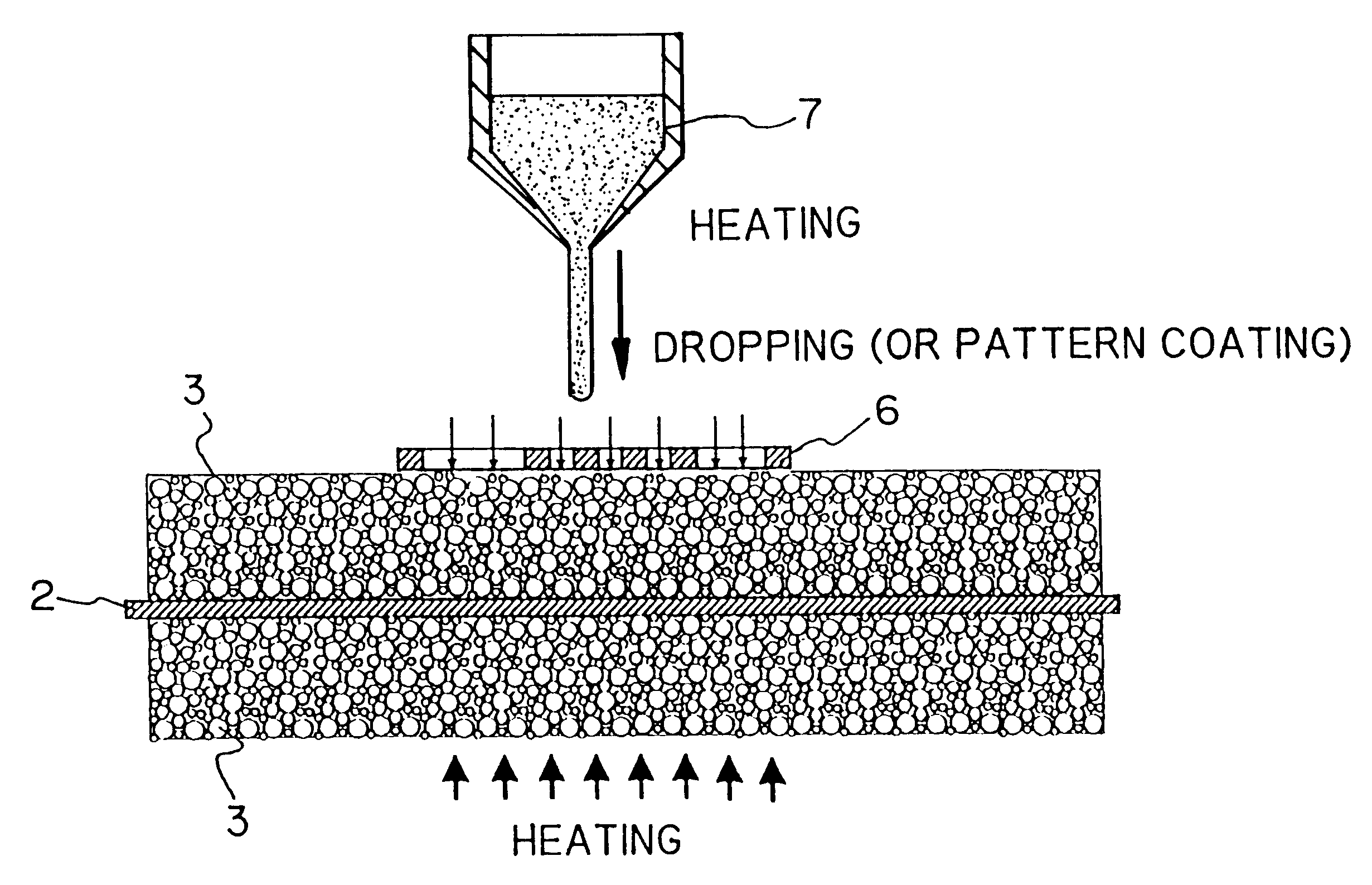
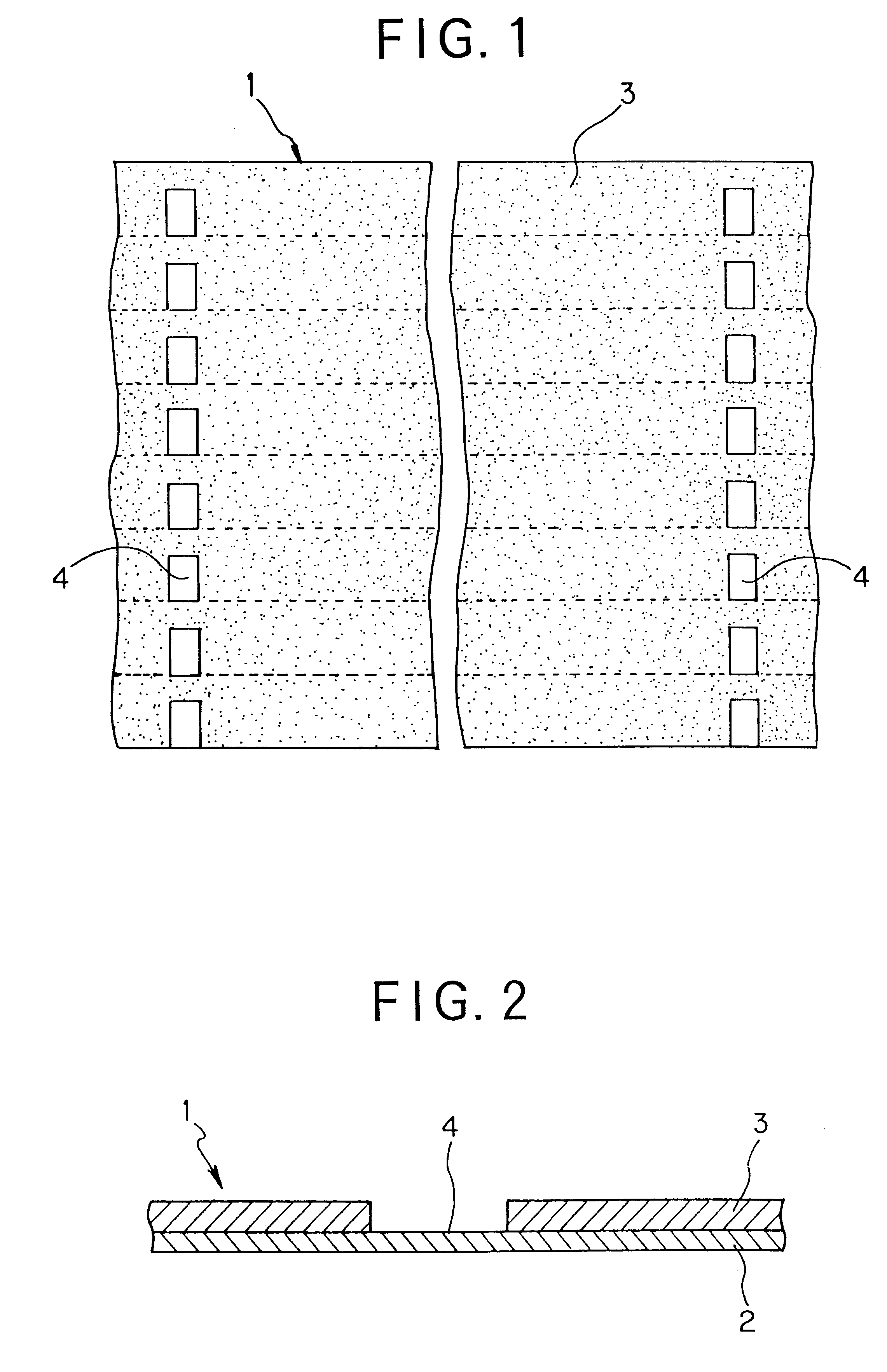
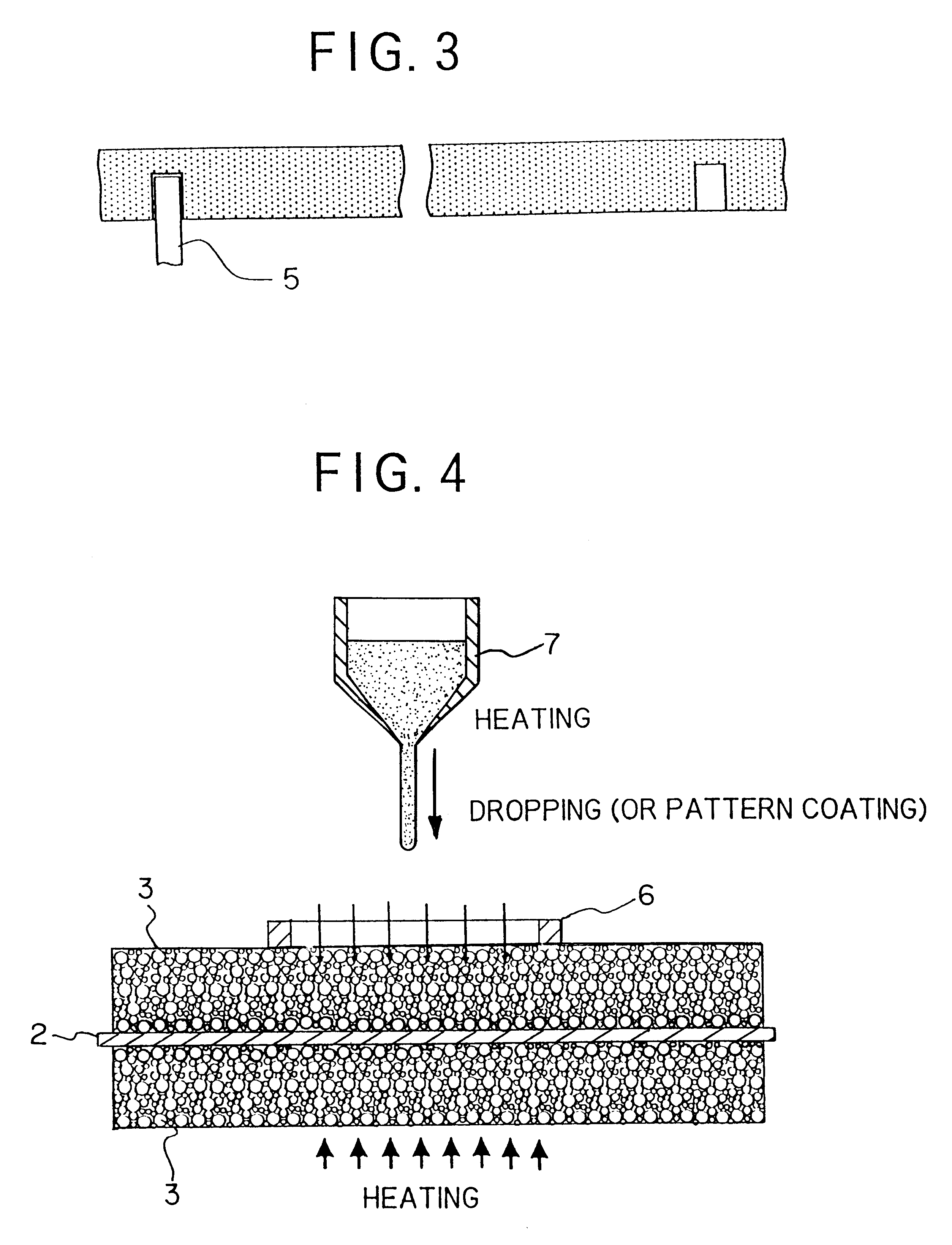
The thus prepared electrode plates for the positive and negative electrodes were placed on a hot plate heated to a temperature of 120.degree. C., and polyethylene (having the product name of "SANWAX 161P" manufactured by SANYO CHEMICAL INDUSTRIES, LTD.), which has been heated to a temperature of 250.degree. C. to melt it, was applied on these electrode plate in a plurality of rectangular shapes each having a width of 3 mm and a length of 7 mm by means of a dispenser through a metallic plate mask corresponding to a negative pattern having a shape shown in FIG. 1. Thereafter, the hot plate was removed and the polyethylene was solidified. The solidified polyethylene provided a strong stiffness, and when it was lifted up by picking up an end portion thereof, the solidified polyethylene was easily removed from the collector with i...

example a-3

Electrode plates for the positive and negative electrodes were prepared under substantially the same applying and drying conditions as those in the Example A-1.

The thus prepared electrode plates for the positive and negative electrodes were heated to a temperature of 70.degree. C. by means of infrared ray lamp, and a wax (having the product name of "DIACARNA 30L manufactured by MITSUBISHI CHEMICAL CORPORATION), which has been heated to a temperature of 160.degree. C. to melt it, was applied on these electrode plates in a plurality of rectangular shapes each having a width of 5 mm and length of 5 mm by means of a dispenser through a metallic plate mask corresponding to a negative pattern having a shape shown in FIG. 1. Thereafter, the infrared ray lamp was removed and the wax was solidified. The solidified wax was hard and easily broken, and the solidified wax portion was naturally raised by applying a tension to the collector and easily peeled off from the collector. The pattern of ...


PUM

PropertyMeasurementUnit
melting viscosityaaaaaaaaaa
melting pointaaaaaaaaaa

Abstract

An electrode plate for a secondary battery with a nonaqueous electrolyte composed of a collector and an active material layer which is formed of at least an active material and a binder disposed on the collector, and the electrode plate is provided with a terminal mounting portion provided with a collector surface exposed to mount a terminal. In such electrode plate, the exposed collector surface of the terminal mounting portion has the same shape and size substantially as those of an area to which the terminal is actually mounted. The electrode plate may further be provided with an identification mark made by forming the active material layer in shape of pattern on an area at which the collector surface is exposed or by exposing the collector surface in the shape of pattern on an area at which the collector is covered with the active material layer.

Description

1. Field of the InventionThe present invention relates to an electrode plate for a secondary battery with a nonaqueous electrolyte, for example, represented by a lithium ion secondary battery and also relates to a process for producing such electrode plate.2. Description of the Related ArtIn recent years, reductions in size and weight of electronic equipments and communication equipments have been rapidly advanced, and therefore, it has also been required to reduce size and weight of a battery used as a driving power source for these equipments. For this request, there has been proposed a secondary battery with a nonaqueous electrolyte represented as a typical example by a lithium ion secondary battery having high energy density and high voltage.There has also been required to propose an electrode plate, which significantly affects on the performance of the secondary battery, having large area of a thin film to elongate a charge / discharge cycle life and obtain a high energy density....

Claims


Application Information

Patent Timeline
Patent Type & Authority Patents(United States)
IPC IPC(8): H01M4/02H01M4/04H01M4/13H01M4/139
CPCH01M4/04H01M4/0404H01M4/0409H01M4/0411H01M4/0414H01M4/0416H01M4/0435H01M4/0483H01M4/13H01M4/139H01M4/0433Y10T29/49115Y02E60/122Y02E60/10
Inventor MIYAZAKI, YUICHIMIYANOWAKI, SHINTAKAHARA, HIDETAKE
Owner DAI NIPPON PRINTING CO LTD
Learn More