Power take off from an endless conveyor

a conveyor and power technology, applied in the direction of conveyors, conveyor parts, transportation and packaging, etc., can solve the problems of chain stretch and wear between the links, high hydraulic standards, and high pressure and fluid volume required to operate these devices, and achieve the effect of increasing li

Inactive Publication Date: 2001-11-27
MARTIN BULK HANDLING SOLUTIONS (PTY) LTD
View PDF15 Cites 39 Cited by
  • Summary
  • Abstract
  • Description
  • Claims
  • Application Information

AI Technical Summary

Benefits of technology

The pressure and volume of fluid required to operate these devices would be very low by hydraulic standards. Small pumps operating at slow rpm would provide sufficient fluid at pressure without the need of a large reservoir. The amount of wear taking place on the cleaning elements can be measured in thousands of a millimeter per hour, therefore very little volume of oil is required, and is largely a case of maintaining a constant pressure to the actuators. Because of the low pressure and volume requirement, very little heat would be generated and power absorbed by the pump would also be small. Large diameter drums in the conveyor belt system would be ideal to use as the prime mover for the pump due to their low revolutions. The pump would be rotating slowly (in the order of 50 to 100 rpm) which would prolong the life of the pump and generate less heat, ensuring reliability.
When wears takes place on the cleaning device, pressure in the circuit will automatically keep tension on the cleaning device, ensuring self adjustment throughout its life at a constant pre-determined cleaning pressure.

Problems solved by technology

In all these devices, as they are used, wear takes place and regular adjustments is required.
These chains stretch and wear takes place between the links.
This relaxing of the component being operated would dislodge any material built up around the operating mechanism and not allow cylinders to stick in a position.
The pressure and volume of fluid required to operate these devices would be very low by hydraulic standards.
Because of the low pressure and volume requirement, very little heat would be generated and power absorbed by the pump would also be small.
These adjusting methods do not provide constant cleaning pressure nor do they provide total self adjustment throughout the cleaner's life.
Compressed air actuators charged from a ring main can be used to provide this self adjusting feature, but compressed air is not always available or financially viable.
In remote locations away from a plant's main activity it would be costly to pipe air over long distances.
Remote locations tend to be neglected and adjustment of belt cleaning equipment likely to be infrequent.
Once a cleaning device is out of adjustment or cleaning pressure drop off occurs, carry back of material is experienced, with debris then falling off along the length of the return run.
Inevitably this has to be cleaned up before costly damage occurs to return rollers and belt which increases operating costs for the user.
Little maintenance would be required as lubrication will be provided by the flow of oil and would also dissipate any heat generated.
This puts unnecessary strain on the components of the belt cleaner at shut down periods.
This tends to dislodge any material that has built up around the cleaner and any dust around the mechanism.
This causes unnecessary wear to both belt cover and cleaner element.
Mechanical joints in an endless conveyor are a particular problem in that the scraper / cleaner is impacted at high speed as the raised joint passes through the scraper / cleaner.
The joint can be damaged by this impact creating costly repairs and downtime.
The scraper / cleaner wearing edge can also be damaged by these repetitive blows, tearing lumps out of the blade edge.
Should a leak develop in the system and the reservoir run dry, the pressure in the circuit would drop and the pressure switch cause the removal of power to the conveyor system.

Method used


Image

  • Power take off from an endless conveyor
  • Power take off from an endless conveyor
  • Power take off from an endless conveyor

Examples


Embodiment Construction

In the description of embodiments shown in several of the Figures, the same reference numerals are used to denote similar components even when installed in different locations.

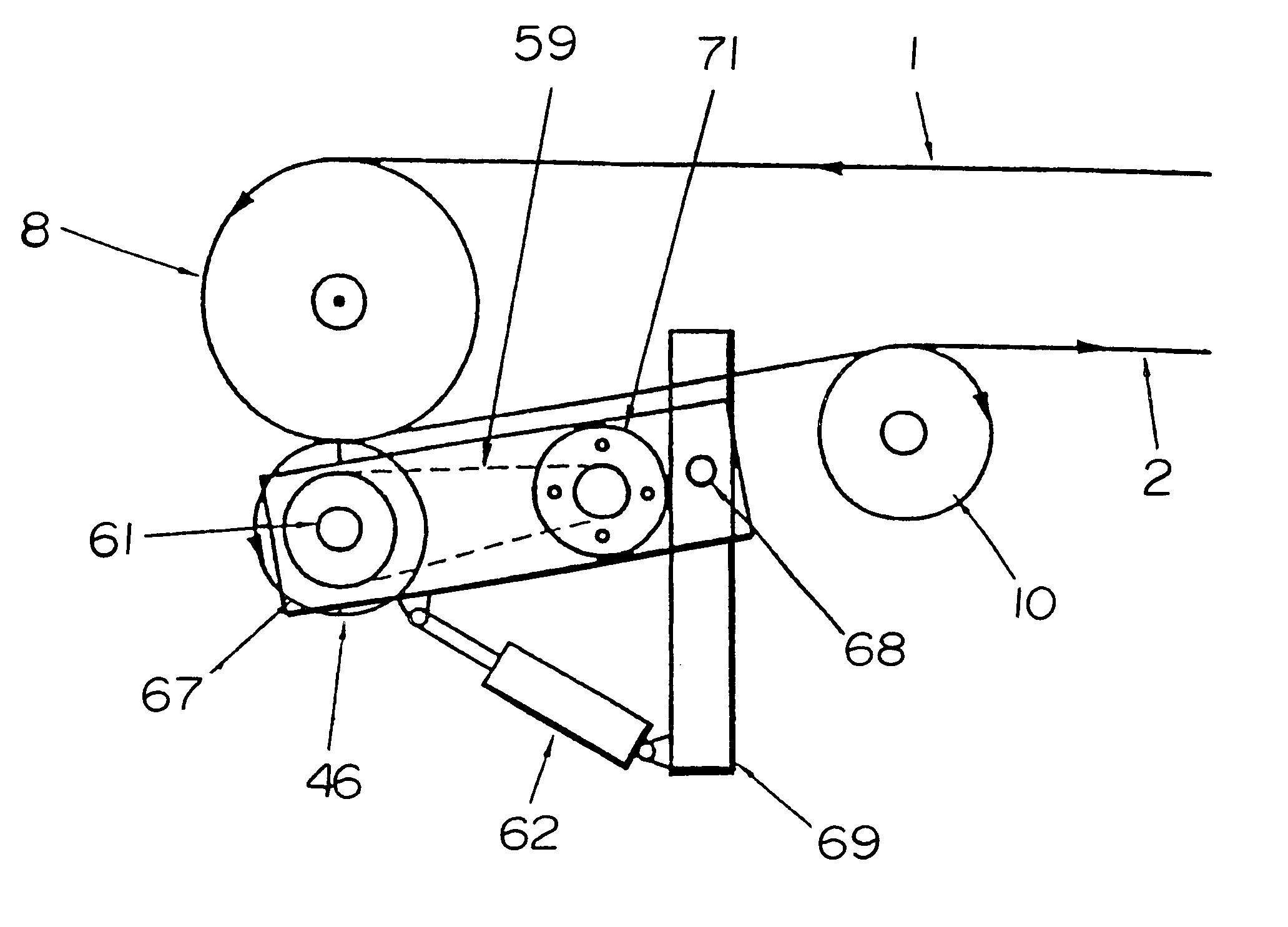
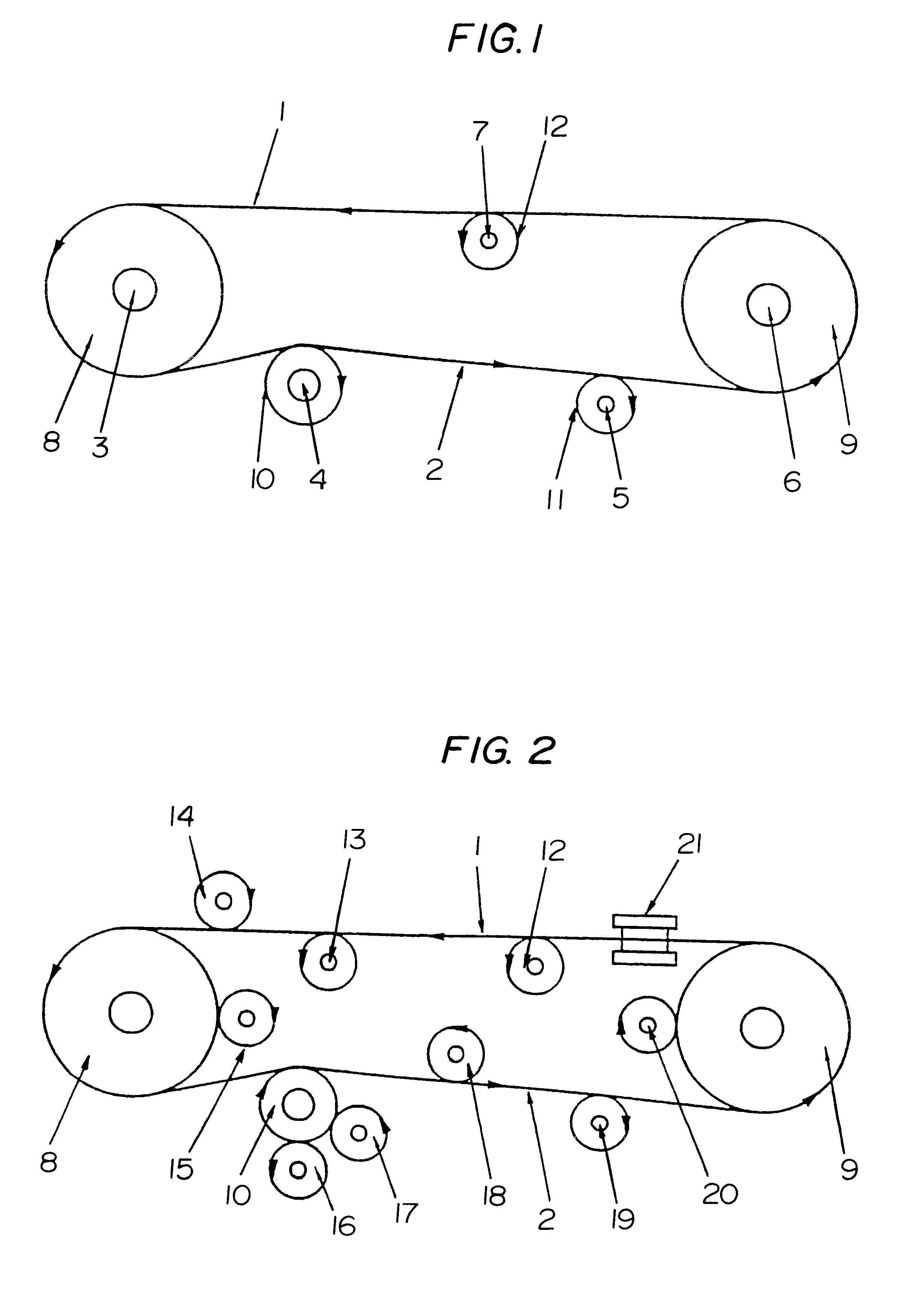
Referring first to FIG. 1, and endless conveyor comprises a belt system having an upper material run 1 and a lower return run 2. Roller shafts 3,4,5,6, and 7 may be utilised to drive an hydraulic pump. Connection between the roller shafts and the pump may be by any suitable means eg muff coupling, bolted coupling, flexible drive cable, two gears meshing together or a gear on the roller shaft driving a gear on the pump shaft via a toothed belt. A freewheel clutch may also be used to connect a roller shaft to the pump so that on reversing conveyors no drive takes place when running in reverse direction. The direction of rotation of head drum 8, return drum 9 and belt idler rollers 11 and 12 are shown in the sketch.

Referring now to FIG. 2, and endless conveyor with an upper conveyor run 1 and a lower return run 2...


PUM


Abstract

A hydraulic power take off device for an endless conveyor belt system having an upper material run and a lower return run, said device being arranged to generate hydraulic fluid at pressure to maintain a self adjusting force to belt cleaning equipment, and other equipment that can utilize fluid pressure. The take off device is driven directly or indirectly from the motion of the conveyor belt or from the motion of other components fitted to the endless system. The power take off comprises a hydraulic pump which is rotated by the motion of the endless conveyor and generates fluid at pressure via an adjustable relief valve and maintains a constant self adjusting force of actuators, automatically compensating for wear that takes place on the equipment being operated and providing an automatic and interlocked source of power, generating pressure only when the conveyor belt system operates.

Description

This invention relates to the deriving of hydraulic power from the linear or rotary motion of an endless conveyor belt or the linear or rotary motion of other components or devices fitted to an endless conveyor belt, said conveyor being of the type having an upper conveyor run and a lower return run.BACKGROUND AND GENERAL DESCRIPTION OF THE INVENTIONAccording to one aspect of the invention, there is provided a power take off device for an endless conveyor belt system of the type comprising an endless belt having an upper conveyor run for transporting material and a lower return run, the power take off device comprising an hydraulic pump operably linked to the belt or to a rotating component forming part of the conveyor belt system so as to generate hydraulic fluid at pressure only when the conveyor belt is in motion.In another aspect, the invention provides a conveyor belt system incorporating a power take off device as defined above.For convenience hereinafter an endless conveyor s...

Claims


Application Information

Patent Timeline
Patent Type & Authority Patents(United States)
IPC IPC(8): B65G45/00B65G23/00
CPCB65G23/00B65G45/00B65G45/16
Inventor MICKLETHWAITE, BARRY
Owner MARTIN BULK HANDLING SOLUTIONS (PTY) LTD
Why Eureka
Try Eureka