Radio selective call receiver and channel selecting method thereof

a call receiver and selective technology, applied in the field of radio selective call receivers, can solve the problems of frequent changeover or handover from one area to another, failure to receive selective calling signals, and long average time length needed for achieving re-synchronization

Inactive Publication Date: 2001-11-27
NEC CORP
View PDF10 Cites 11 Cited by
  • Summary
  • Abstract
  • Description
  • Claims
  • Application Information

AI Technical Summary

Benefits of technology

Another object of the present invention is to provide a radio selective call receiver which enables automatic selection of the channels with a lower power consumption.
As described above, it is again determined whether the previous sync established channel (the first radio channel) is now qualified for reception when switching to the second radio channel. If the first radio channel is available for sufficient reception, the first radio channel that was selected previously is again selected with making no channel change. Accordingly, it is possible to prevent execution of unnecessary area changeovers due to temporary deterioration in radio condition and to achieve an increase in the life of the battery and an increase in the efficiency with which the sync pull-in operation is performed.
When the second radio channel has been found through the channel scanning, the condition of the first radio channel that was a previously sync established channel is again checked. Therefore, under the circumstances wherein area changeover is properly needed, the area changeover can be performed smoothly.
Further, since the quality of the second radio channel is relatively decreased in a predetermined ratio with respect to the quality of the first radio channel and then the comparison is made, it is possible to prevent execution of unnecessary area changeovers due to temporary deterioration in radio condition and to achieve an increase in the life of the battery and an increase in the efficiency with which the sync pull-in operation is performed.

Problems solved by technology

For this reason, in a case where adjacent radio areas are overlapped, it results that a changeover or handover from one area to another frequently occurs.
Therefore, when area changeover is not in time, there is the possibility that the failure to receive the selective calling signal will occur.
In this method, however, an unnecessary period of time for determining the synchronization of the last synchronized channel is needed and therefore the average time length needed for achieving a re-synchronization becomes long.
As a result, the battery life becomes inconveniently short.
Further, in a case where the status of the electric field becomes bad at the point in time when determining the synchronization of the last synchronized channel, the receiver becomes synchronized with an available channel that has been first detected.
For this reason, there is the possibility that area changeover will frequently occur.

Method used


Image

  • Radio selective call receiver and channel selecting method thereof
  • Radio selective call receiver and channel selecting method thereof
  • Radio selective call receiver and channel selecting method thereof

Examples


second embodiment

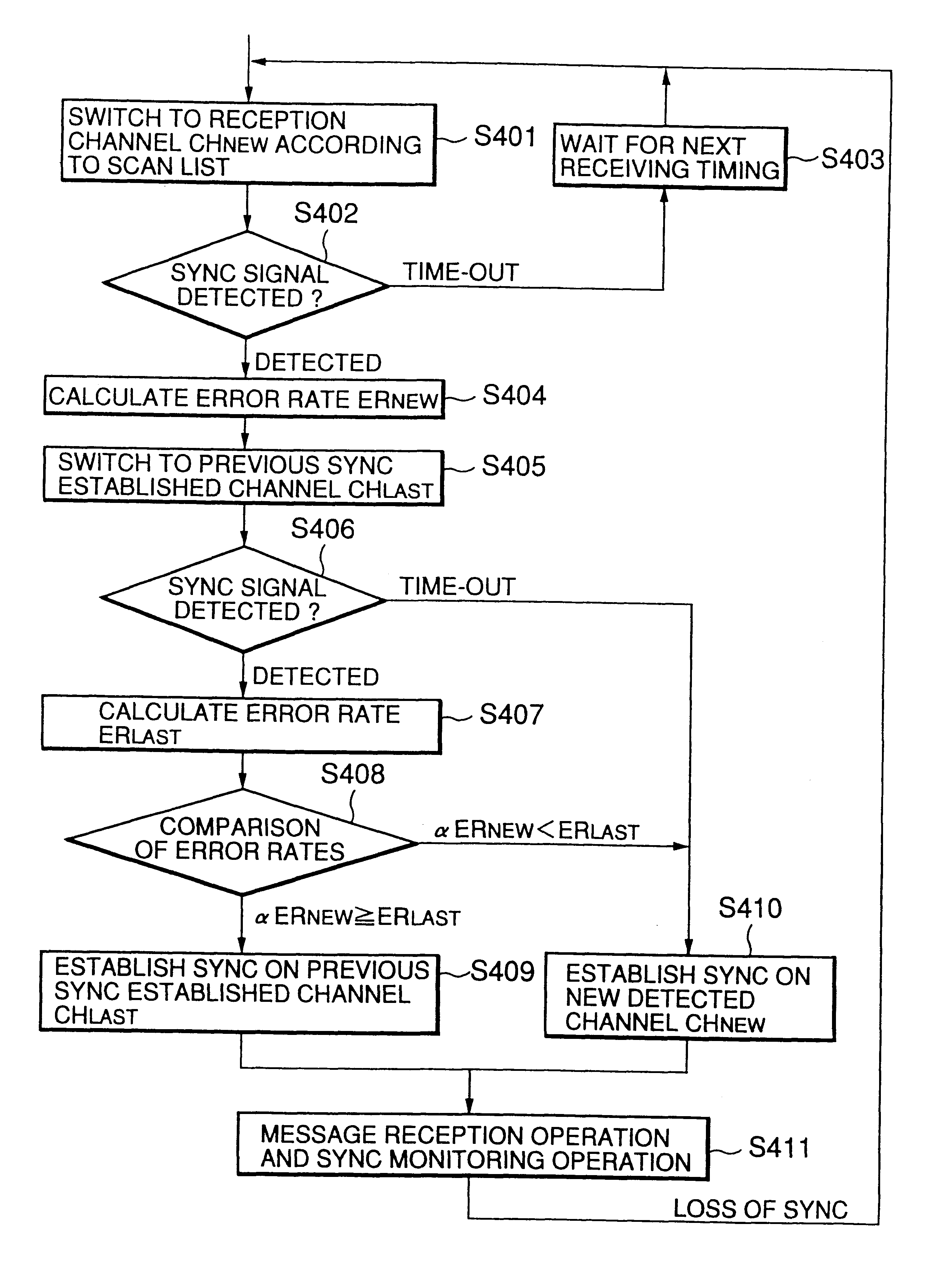
Referring to FIG. 4, there is shown a second embodiment of the automatic channel selecting method according to the present invention. The second embodiment is directed to making channel selection by taking the channel quality into consideration. Specifically, the error rate is calculated based on the error correcting operation by the error-correcting decoder 104 and the error rate is used as a basis for making channel selection. The second embodiment will hereinafter be described in detail.

When loss of synchronism is detected by the synchronization section 105 due to the movement of the user to outside the radio zone or to the temporary decrease in the reception intensity, the processor 107 stores therein the latest sync established channel CH.sub.LAST with which the receiver was synchronized. Thereafter, in order to search for an available channel with which the receiver is to be synchronized, the processor 107 performs the scanning of the channels in accordance with the predetermi...

third embodiment

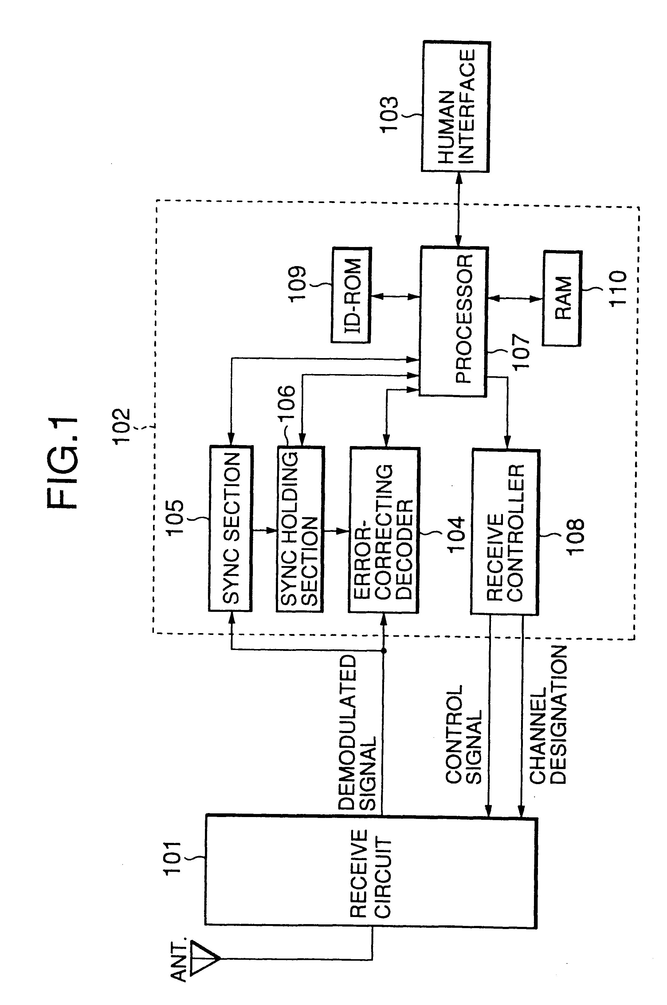
Referring to FIG. 5, there is shown a radio selective call receiver employing a channel selection method according to the third embodiment of the present invention. In this diagram, circuit blocks similar to those previously described with reference to FIG. 1 are denoted by the same reference numerals and the explanations thereof will be omitted.

The receive circuit 101 outputs a received electric field level RSS corresponding to the demodulated signal to the control section 102. The received electric field level RSS is converted to a digital signal by an analog / digital converter 501 and the digital electric field level RSS is used in the processor 107 as a basis for making channel selection, which will be described hereinafter.

Referring to FIG. 6, there is shown the third embodiment of the automatic channel selecting method according to the present invention. The third embodiment is directed to making channel selection by taking the channel quality into consideration.

When loss of sy...


PUM


Abstract

In a radio selective call receiver, a reception channel is efficiently selected from a plurality of radio channels without unnecessary channel switch. When having lost synchronism with a first radio channel, the radio channels are scanned in a predetermined sequential order to search for a second radio channel with which synchronization is established. When the second radio channel has been found, it is again determined whether synchronization can be established with the first radio channel. When synchronization has been established with the first radio channel, the first radio channel is selected as the reception channel. When synchronization fails to be established with the first radio channel, the second radio channel is selected as the reception channel.

Description

1. Field of the InventionThe present invention relates to a radio selective call receiver and, more particularly, to a method for automatically selecting a reception channel from a plurality of channels.2. Description of the Related ArtThere has been disclosed an example of a radio selective call receiver having the function of automatically switching a reception area in Japanese Patent Application Laid-Open Publication No. 6-315001. This conventional example is used in a system which is composed of a plurality of radio areas (small zones) each having a different frequency. When the state of the receiver comes out of synchronization with a selective calling signal, the sweep of the frequency channels is performed a prescribed number of times in accordance with a scan list. Then, when no synchronization signal has been detected, the operation of the radio system is stopped and, after the lapse of a prescribed time period, the sweep of the frequency channels is performed again.However...

Claims


Application Information

Patent Timeline
Patent Type & Authority Patents(United States)
IPC IPC(8): H04Q7/18H04W88/02
CPCH04W88/022
Inventor MIYASHITA, MAFUMI
Owner NEC CORP
Why Eureka
Try Eureka