Supercharge Your Innovation With Domain-Expert AI Agents!

Power amplifier, power control method for power amplifier, and communication equipment

a technology of power amplifiers and control methods, applied in the direction of amplifiers, gated amplifiers, electrical apparatuses, etc., can solve the problems of poor efficiency, poor distortion, and a large consumption of battery power

Inactive Publication Date: 2001-12-11
PANASONIC CORP
View PDF6 Cites 16 Cited by
  • Summary
  • Abstract
  • Description
  • Claims
  • Application Information

AI Technical Summary

Benefits of technology

As described above, in the power amplifier of the invention, in accordance with reduction of the transmission power, the amplifier of a higher power is bypassed by the high-frequency switch, and the power source of the bypassed amplifier is cut off, whereby the efficiency in transmission at a low power can be improved. By repeating this operation, the efficiency can be improved in a broad dynamic range in transmission.Furthermore, the initial current of the amplifier itself of each stage is reduced so that the amplifier operates in a manner similar to that of Class B, whereby the efficiency at a low output power can be improved. In this case, although distortion of a higher degree appears in the amplifiers, predistortion compensation is performed by using transistors of the high-frequency switch in the bypass circuit. Therefore, a power amplifier can be realized in which the initial current is low in level and an unnecessary current is interrupted at a low output power can be realized without increasing the circuit scale.

Problems solved by technology

However as shown in FIG. 14, in the case where the initial currents are set to be similar to those in the TDMA system, the efficiency becomes poor because the consumed current at low output is large.
On the contrary when the initial currents are half, the amount of distortion near maximum output becomes poor.
In the CDMA system, particularly, the time period when transmission is performed at a power of a reduced level is longer than that when transmission is performed at the maximum power, and therefore the battery power is largely consumed, with the result that the talk time is shortened.
In this case, however, the distortion level is impaired.
Therefore, the reduction of the initial current is limited.

Method used


Image

  • Power amplifier, power control method for power amplifier, and communication equipment
  • Power amplifier, power control method for power amplifier, and communication equipment
  • Power amplifier, power control method for power amplifier, and communication equipment

Examples


embodiment 1

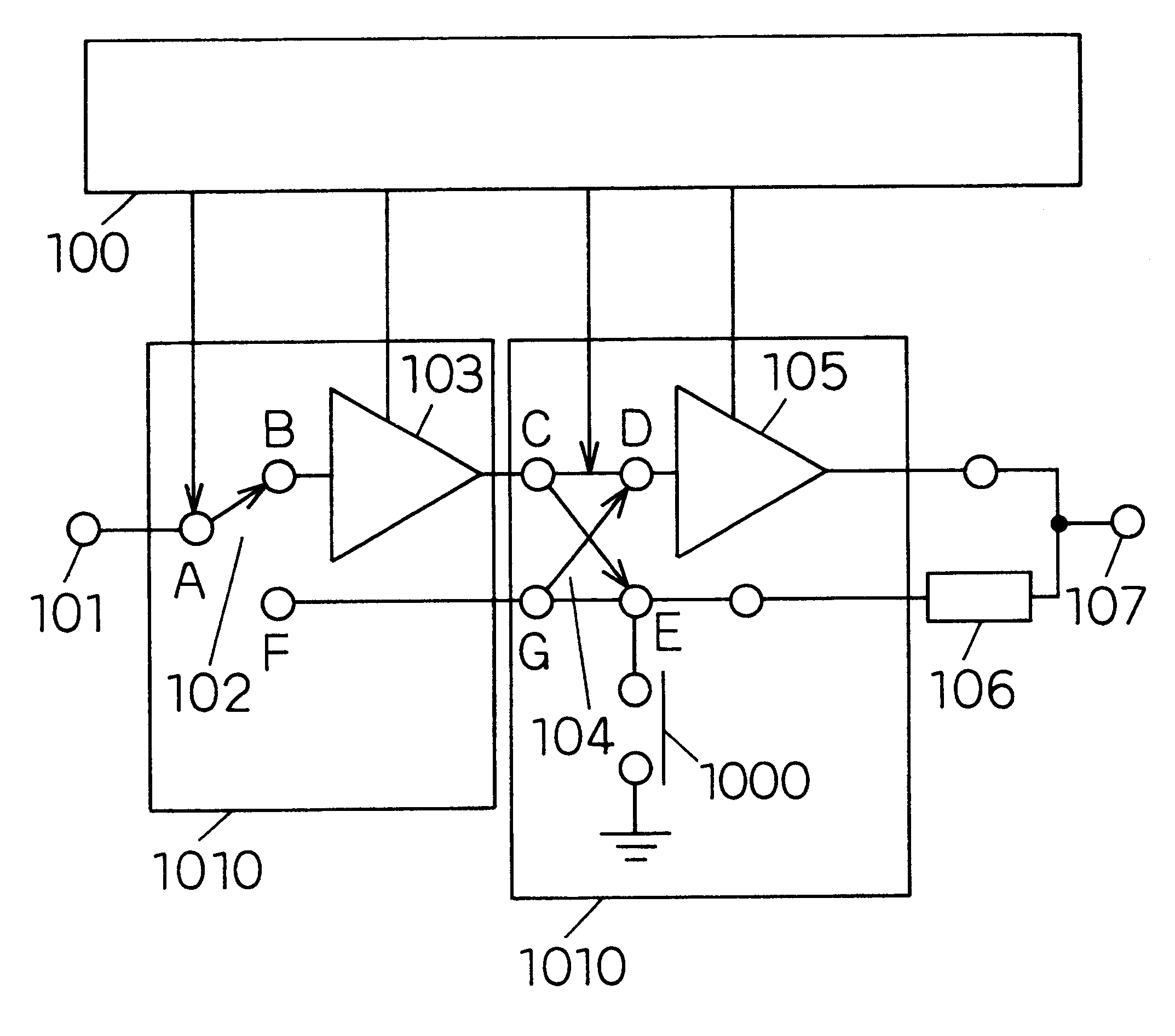
A first embodiment of the invention will be described with reference to FIGS. 1 and 2. FIG. 1 is a block diagram of a power amplifier of the first embodiment. The reference numeral 100 denotes a bias control circuit, 101 denotes an input terminal, 102 denotes a first high-frequency switch circuit which switches one input to two outputs, 103 denotes a preamplifier, 104 denotes a second high-frequency switch circuit which independently switches two inputs to two outputs, 105 denotes a postamplifier, 106 denotes a quarter wavelength line (impedance conversion circuit), and 107 denotes an output terminal. The amplification circuit 1010 according to the invention is a combination of the high-frequency switch circuits and the amplifiers.

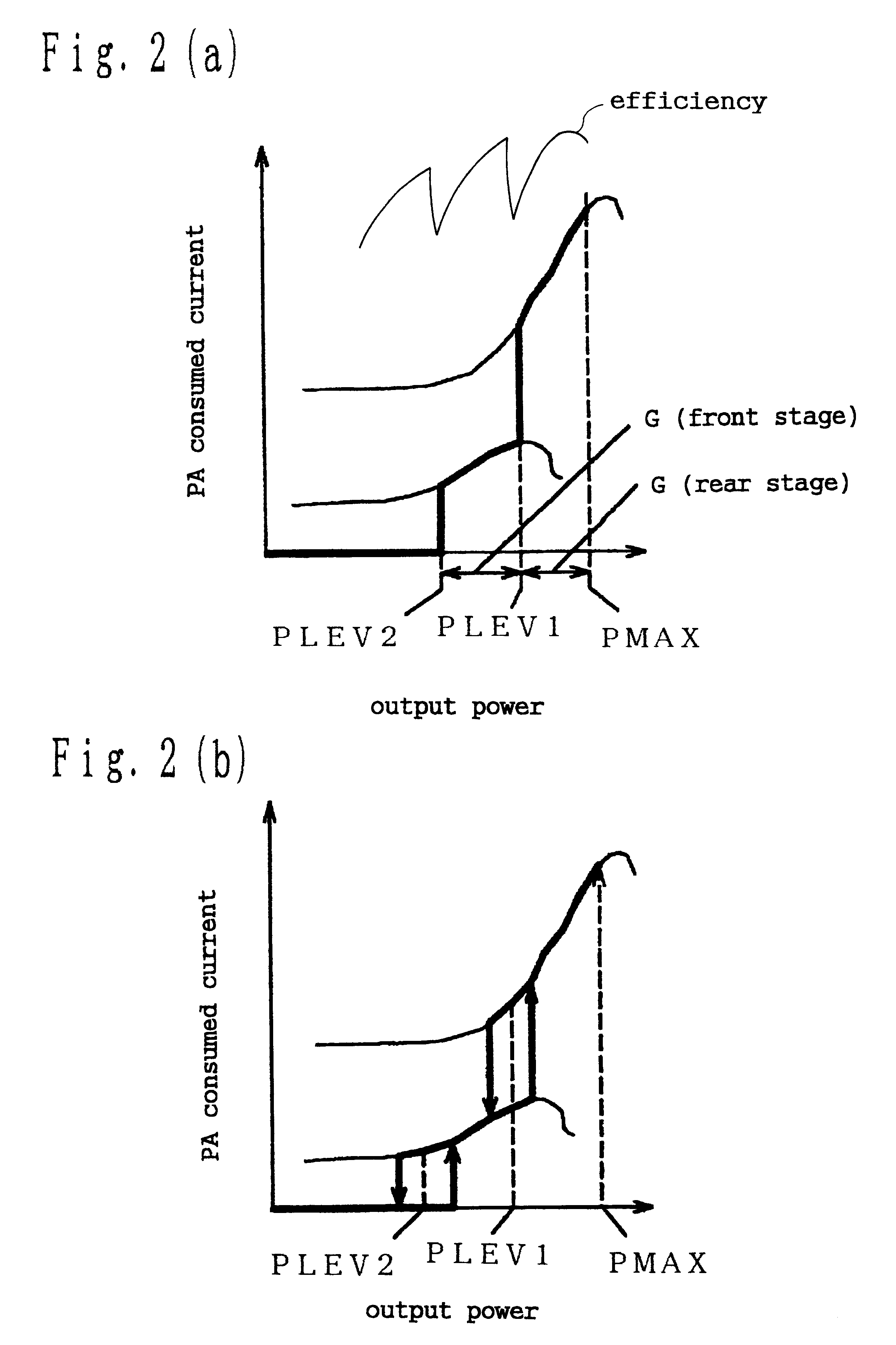
In the power amplifier of the embodiment, when the maximum power must be output, connection between A and B is made in the first high-frequency switch circuit 102, and connection between C and D is made in the second switch. At this time, the impedance of ...

embodiment 2

A second embodiment of the invention will be described with reference to FIG. 3. FIG. 3 is a block diagram of a power amplifier of the second embodiment. The reference numeral 300 denotes a bias control circuit , 301 denotes an input terminal, 302 denotes a first high-frequency switch circuit which switches one input to two outputs, 303 denotes a preamplifier, 304 denotes a second high-frequency switch circuit which independently switches two inputs to two outputs, 305 denotes a middle amplifier, 306 denotes a third high-frequency switch circuit which independently switches two inputs to two outputs, 307 denotes a postamplifier, 308 denotes a quarter wavelength line, and 309 denotes an output terminal.

The power amplifier of the second embodiment of the invention is configured by: the input terminal 301; the first high-frequency switch circuit 302 which switches a signal input via the input terminal 301 to two outputs; the first amplifier (preamplifier) 303 which is connected to one ...

embodiment 3

A third embodiment of the invention will be described with reference to FIG. 5. FIG. 5 is a block diagram of a power amplifier of the third embodiment. The reference numeral 400 denotes a bias control circuit, 401 denotes an input terminal, 402 denotes a first high-frequency switch circuit which switches one input to two outputs, 403 denotes a preamplifier, 404 denotes a second high-frequency switch circuit which independently switches two inputs to two outputs, 405 denotes a postamplifier, 406 denotes a quarter wavelength line, 407 denotes an output terminal, 408 denotes a first predistortion circuit which previously compensates distortion generated in the preamplifier, and 409 denotes a second predistortion circuit which previously compensates distortion generated in the postamplifier.

The power amplifier of the third embodiment of the invention is characterized in that, in addition to the configuration of the first embodiment, the first predistortion circuit (first predistortion c...


PUM


Abstract

A power amplifier has an input terminal; an output terminal; an N number of bypassable amplification circuits which are connected directly or indirectly in a sequential manner between the input terminal and the output terminal; an impedance conversion circuit which is connected directly or indirectly between the amplification circuit of a final stage and the output terminal; and a bias control circuit which controls the amplification circuits,each of the amplification circuits is configured by a high-frequency switch circuit, and an amplifier which is connected directly or indirectly to the switch circuit, andthe bias control circuit controls power source voltages of the amplifiers and controls status of the switch circuit.

Description

1. Field of the InventionThe present invention relates to a power amplifier, a control method for such a power amplifier, and a communication equipment which are used mainly in a mobile communication system.2. Related Art of the InventionRecently, digital mobile communication system rapidly enters widespread use, and miniaturization of a communication terminal, and reduction of power consumption are advancing. As a successor to a currently used digital portable telephone, also a portable telephone using the CDMA (Code Division Multiple Access) system which can ensure a larger communication capacity is being developed. The CDMA system is described in detail in "CDMA HOSHIKI TO JISEDAI IDOTAI TSUSHIN SYSTEM" (Chap. 1, TRORIKEPSU SOSHO), and hence its detailed description is omitted.Hereinafter, a power amplifier of the conventional art will be described with reference to FIGS. 13 and 14. FIG. 13. is a diagram showing the configuration of power amplifier of the convention art. Referrin...

Claims


Application Information

Patent Timeline
IPC IPC(8): H03F1/02H03F3/72
CPCH03F1/0277H03F1/0288H03F3/72H03F2203/7239
Inventor ISHIDA, KAORUOBARA, TOSHIOKOSUGI, HIROAKIKOMATSU, NAOKI
Owner PANASONIC CORP
Features
  • R&D
  • Intellectual Property
  • Life Sciences
  • Materials
  • Tech Scout
  • Unparalleled Data Quality
  • Higher Quality Content
  • 60% Fewer Hallucinations
Learn More