Ceramic tile armor with enhanced joint and edge protection

a ceramic tile and joint technology, applied in the field of ceramic tile armor, can solve the problems of large individual tiles not being able to adapt to as great an arrangement of surface configurations, reducing the protection value of ceramic armor, and affecting the appearance of the protective garmen

Inactive Publication Date: 2001-12-25
SIMULA
View PDF15 Cites 84 Cited by
  • Summary
  • Abstract
  • Description
  • Claims
  • Application Information

AI Technical Summary

Benefits of technology

It is a further object of the invention to provide armor joint and free-edge reinforcement with a minimal increase in weight to the overall armor configuration.
Another object of the invention is to provide ceramic tile armor with joint and free-edge protection at higher reliability and lower production costs than those associated with prior art methods.

Problems solved by technology

However, it is also known that the protective value of ceramic armor progressively degrades as impact points approach the edges, corners, and abutting joints between individual tiles.
These improvements, however, have limitations.
Large individual tiles are not adaptable to as great an arrangement of surface configurations as are small tiles.
As a result of this increased crack propagation, a greater percentage of the overall armor is therefore damaged than would be the case with smaller tiles.
Raised-edge enhancements improve the tile's protective performance, but are more difficult and costly to manufacture than flat, constant-thickness tiles.
Both these improvements, however, are limited solely to the protection of the free edges of ceramic composite tile armor.
They cannot be applied to the similarly vulnerable corners and abutting joints between individual ceramic armor tiles.
This enhancement is effective in improving ballistic protection, but is both costly and difficult to manufacture.
Once the ceramic tiles are in place, there is no cost-effective method to assure that the metallic strips remain placed as intended as the entire armor assembly is cured.

Method used


Image

  • Ceramic tile armor with enhanced joint and edge protection
  • Ceramic tile armor with enhanced joint and edge protection
  • Ceramic tile armor with enhanced joint and edge protection

Examples


Embodiment Construction

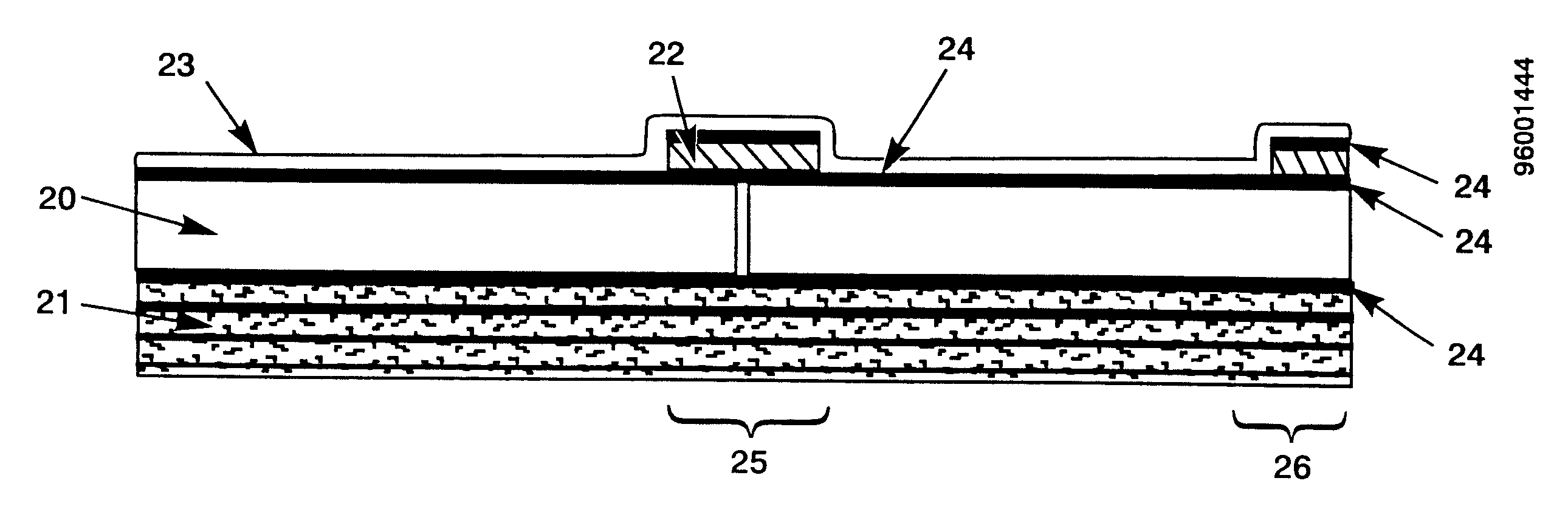
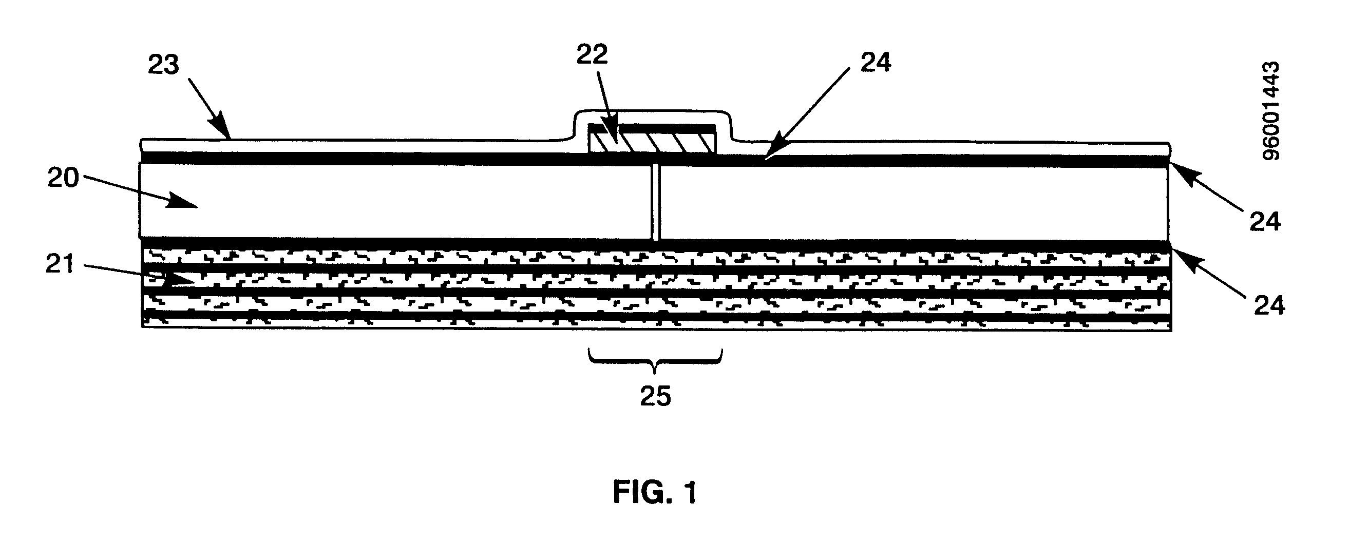
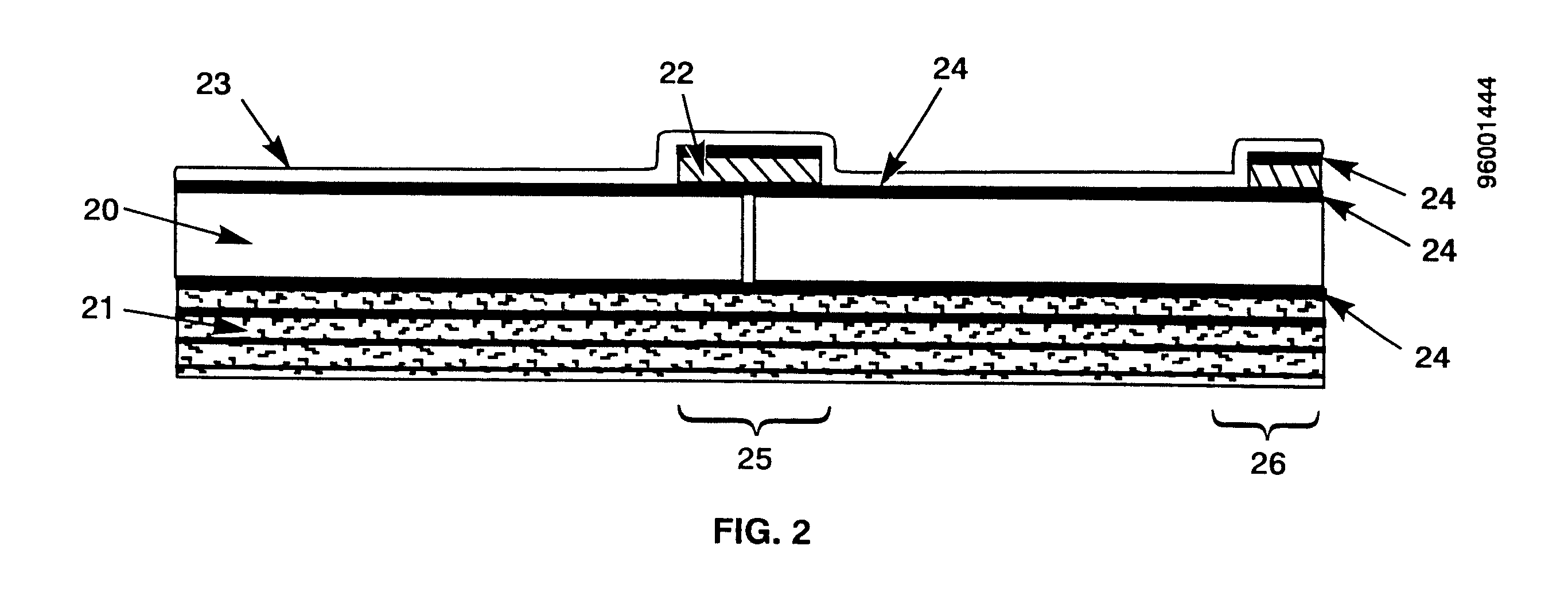
The construction of the preferred embodiment of the ceramic tile armor is shown in FIGS. 1 and 2. Ceramic tile 20 is bonded to a laminate backing 21, and strips 22 of glass or ceramic are bonded to a joint area 25 and a free-edge area 26 of the ceramic tile 20. A spall shield 23 is bonded over the tile 20 and strips 22. The components are bonded together using a resin adhesive 24.

The ceramic tile 20 is preferably made of aluminum oxide, silicon carbide, or boron carbide depending on the weight, performance, and cost requirements involved. Other suitable tile materials include ceramic matrix composites (CMCs) such as silicon carbide / aluminum, which may provide improved multi-hit resistance due to their higher fracture toughness. The laminate backing 21 is preferably composed of a fiberglass, aramid, or polyethylene fiber-reinforced laminate with a polyester, vinylester, epoxy, phenolic, or other resin matrix component, and is produced in a manner typical of laminate construction. Pre...


PUM

PropertyMeasurementUnit
angleaaaaaaaaaa
thicknessaaaaaaaaaa
thicknessaaaaaaaaaa

Abstract

A ceramic composite tile armor which is reinforced at the more vulnerable joint and free edge areas, using glass or ceramic strips or overlays bonded with an adhesive to the outer surface of the tile joints and free edges. This reinforcement provides improved ballistic threat protection for ground vehicle, aircraft, watercraft, spacecraft, and body (personnel) ceramic tile armor applications. Glass or ceramic overlay strips assist in fracturing impacting projectiles that strike the tile joints or free edges. The substrate laminate backing can then capture fragments of the projectile and broken ceramic and prevent penetration. The invention provides improved protection over conventional joint and edge enhancements with higher reliability of accurate positioning over joint and free-edge areas, with less added weight, and at lower associated production costs.

Description

1. Field of the InventionThe present invention relates to ceramic and ceramic matrix composite (CMC) tile armor, and specifically to armor that has reinforcement of the joints and free edges of the armor with glass or ceramic strips. These strips, according to the invention, are applied over the ceramic armor joints and edges and thereby increase the armor's ability to withstand a variety of ballistic threats. The purpose of this invention is to provide optimal armor protection capability for ground vehicles, watercraft, aircraft, spacecraft and, in body armor applications, for personnel.2. Background of the InventionLightweight, composite ceramic tile armor has proven an effective countermeasure against a variety of ballistic threats including lead core, steel core, armor-piercing rounds, and fragments. However, it is also known that the protective value of ceramic armor progressively degrades as impact points approach the edges, corners, and abutting joints between individual tile...

Claims


Application Information

Patent Timeline
Patent Type & Authority Patents(United States)
IPC IPC(8): F41H5/04F41H5/00
CPCF41H5/0435
Inventor LYONS, F. STANTON
Owner SIMULA
Why Eureka
Try Eureka