In the conventional
thermal treatment manner as described above, when all the materials to be treated are uniformly heated, kept at their temperatures and cooled during their thermal treatment, a large thermal treatment space is required, and thus a
heat energy loss by means of such a thermal treatment space is also very large.
In order to keep such a large thermal treatment space, there is a problem in that a ratio of a
heat energy which has been effectively consumed by the materials to be treated through the heating treatment (i.e. effectively reserved heat) to a
heat energy which has been supplied to the thermal treatment apparatus is small, so that most of the supplied heat energy is wasted, which leads to a high cost of the thermal treatment.
Further, in the thermal treatment apparatus, the conveyer in addition to the materials to be treated has to be heated, so that a large amount of heat is consumed for heating the conveyer.
In order to heat the conveyer which is of a complicated mechanism and of which
heat capacity is large, a large amount of heat is required.
When the conveyer leaves the
heating furnace, an amount of heat supplied to the conveyer in the thermal treatment apparatus dissipates to the outside so that such heat is wasted.
Every time when the conveyer recirculates to enter and leave the thermal treatment apparatus during its circulation, a large amount of heat is added to the conveyer and such an amount dissipates to the outside without being utilized.
In addition, with the conventional thermal treatment technology, an amount of heat energy lost outside through a wall of the
heating furnace is large, which would be as much as about 45% of the supplied total heat energy.
As a result, it is said that only not more than 5% of the totally supplied energy is used for the thermal treatment of the material to be treated, and thus very ineffective thermal treatment is currently carried out.
However, considering practicability, it is very difficult to carry out floating-transporting control (i.e. to stably halt the object after it has been transported surely in a predetermined period while keeping its predetermined level) by means merely of an action of a gas in a high temperature
atmosphere.
Even though it is possible to carry out doing so, it is easily expected that a cost for means which controls a gas flow rate used for floating and transporting of the substrate would be extremely high.
Also, the temperature (T) cannot be decreased since a cooling apparatus is required when the temperature is lowered below the normal temperature.
On the other hand, when the gas ejection speed is excessively large, some device is required with regard to the gas ejection means such as a
nozzle, and as a result the gas ejection means becomes expensive.
When it is possible to stop the thermal treatment only during the material to be treated is being floated, the thermal treatment may not be carried out upon being floated.
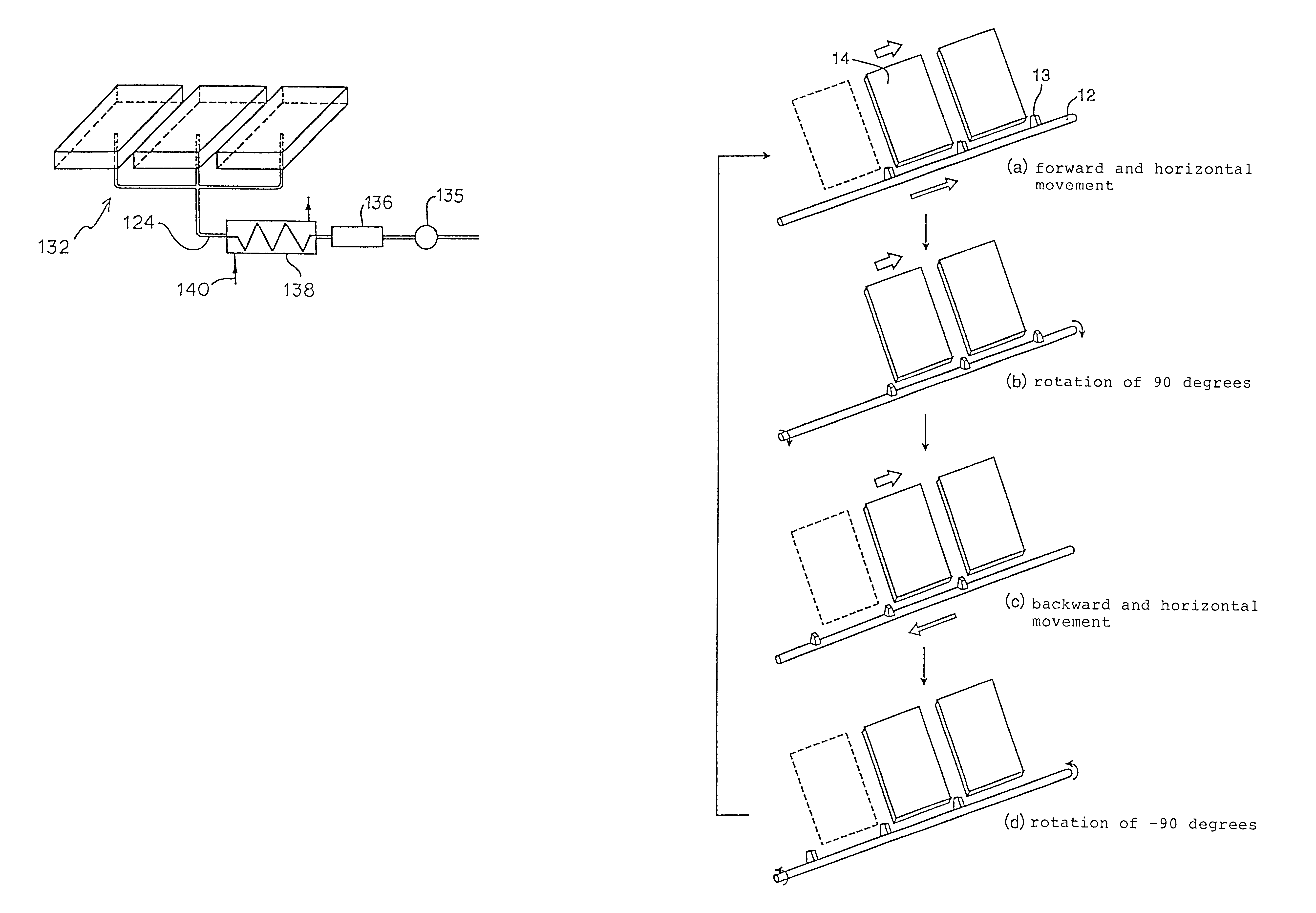
Secondly, transporting the material to be treated along the predetermined direction by means of the transporting means.
However, when the floating level is excessively large, the ejected gas does not contribute to floating, but merely passes through a space between the material to be treated and the base plate and escape from the periphery of the object, which leads to the increase of an amount of the wasted gas.
On the other hand, when the floating level is excessively small, the object may contact the base plate so that a quality of the material to be treated may be degraded.
For example, in the case in which a high temperature gas is ejected from the gas ejection means so that the floating of the material to be treated is intended to be carried out simultaneously with the thermal treatment of the material to be treated, when the high temperature gas is directly ejected to the material to be treated for floating, there may occur broad temperature distribution across the object which results in non-uniform thermal treatment,
thermal strain due to a
residual stress to in the treated material, or breakage of the material to be treated because of rapid heating or cooling.
In addition, a complicated device which transports power to the member can be located outside the thermal treatment space.
Further, due to such deformation, the floating action of the material to be treated may be interrupted.
For example, when the gas is ejected at a high speed, it causes unnecessary matters such as dust which deposits on an inner wall and the like of the thermal treatment space to be scattered, and the thermal treatment space may contain them which may provide adverse effects.
Optionally, a gas clarifying means is necessary which removes from the thermal treatment
atmosphere, gas or particles such as dust which is formed during the thermal treatment and which would otherwise deposit on the material to be treated and adversely affect its quality.
Thus, using such "factory air" as an
atmosphere gas of the thermal treatment and as a floating gas to be ejected directly toward the material to be treated causes the dust to be deposited onto the material to be treated, which results in for example a
short circuit problem where the material to be treated is a kind of an insulation material, and thus often results in a severe quality problem.

