Optical transmitter system and method

a technology of optical transmitters and optical receivers, applied in the direction of digital transmission, transmission monitoring, instruments, etc., can solve the problems of limiting the transmission distance due to chromatic dispersion, and achieve the effects of reducing the receiver sensitivity, facilitating and simple implementation, and reducing the demands on the receiver

Inactive Publication Date: 2002-01-08
TELEFON AB LM ERICSSON (PUBL)
View PDF7 Cites 35 Cited by
  • Summary
  • Abstract
  • Description
  • Claims
  • Application Information

AI Technical Summary

Benefits of technology

An advantage of the invention is that it may into some extent compensate for dispersion in dispersive systems such as a fiber-optic system operating at 1550 nm in standard single mode fibers.
Another advantage is that it needs a lower receiver sensitivity for a given transmission distance as compared with the transmitter system described in prior art.
Still another advantage of the invention is that when the AC-amplifiers ampli

Problems solved by technology

The main problem with a duobinary transmitter as described is that the chromatic dispersion stil

Method used


Image

  • Optical transmitter system and method
  • Optical transmitter system and method
  • Optical transmitter system and method

Examples


Embodiment Construction

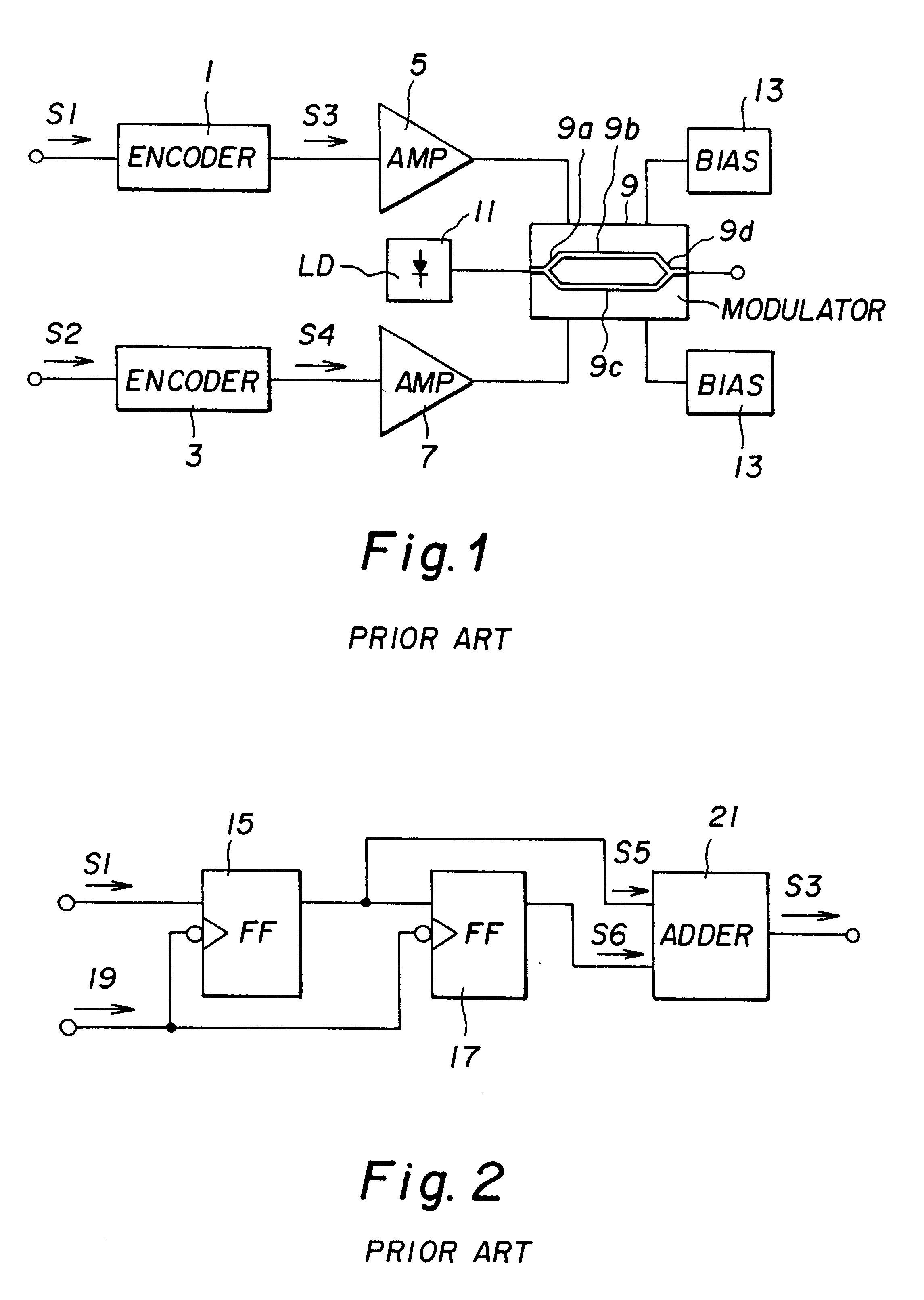
The duobinary transmitter according to the present invention is based on the DEMZ-modulator, but the modulation is completely different compared to the modulation technique as described in prior art.

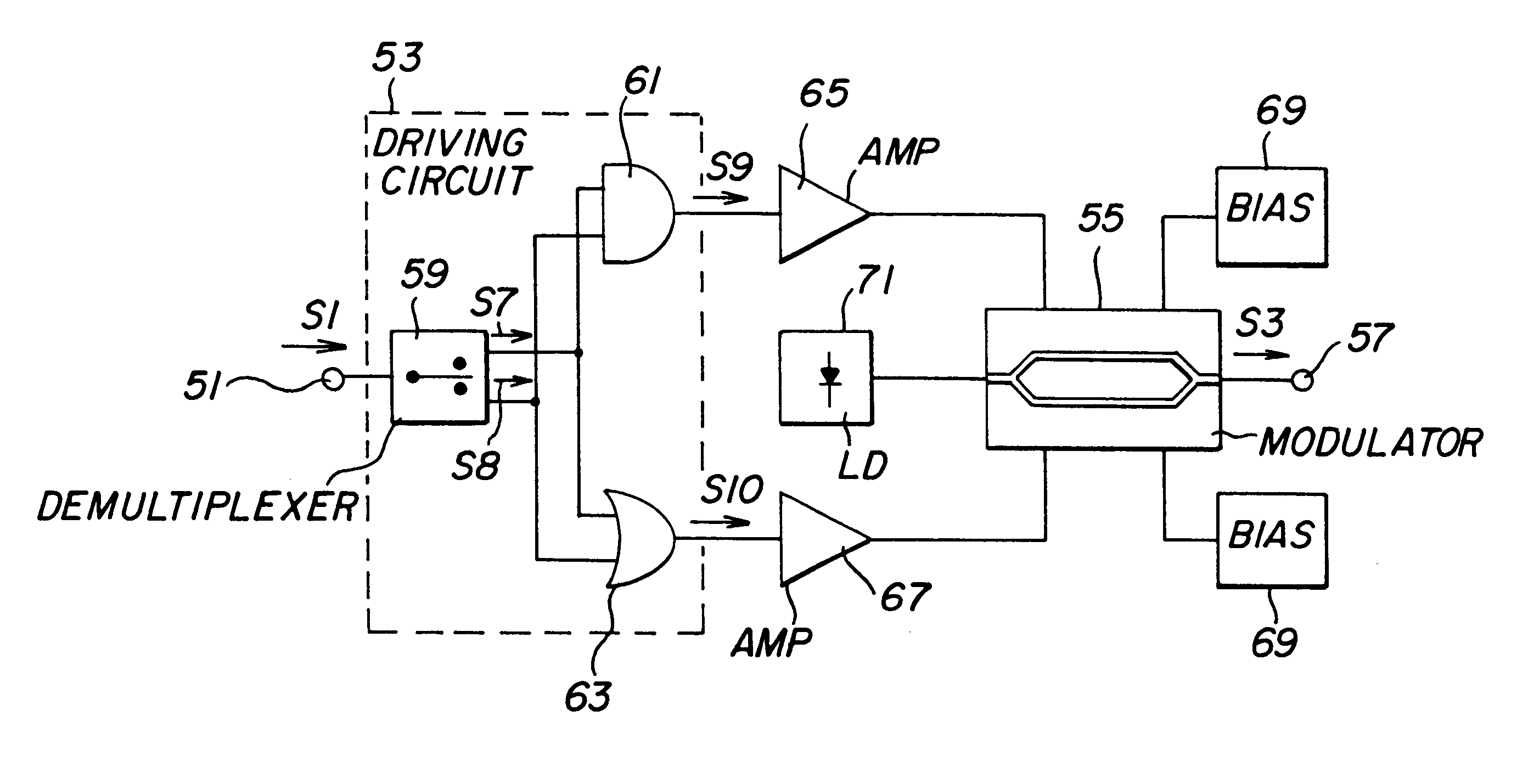
A first preferred embodiment of the present invention will be described with reference to FIG. 5. An optical duobinary transmitter comprises an input terminal 51, a driving circuit 53, a double electrode optical modulator 55, preferably a DEMZ-modulator, and an output terminal 57.

The driving circuit is connected to the input terminal and comprises a demultiplexer 59 and two logical gates 61, 63, preferably an AND- and an OR-gate. The demultiplexer is arranged to demultiplex an input binary signal S1 into two binary signals S7 and S8, each having half the bit-rate of the input binary signal S1. In this case it is essential that these signals change its marks out of phase to each other. For example, an incoming signal sequence ABCDEFGH should be demultiplexed into the sequences AACCEEGG* a...


PUM


Abstract

The present invention relates to an optical duobinary transmitter system and method using optical intensity modulation. The system comprises an input terminal (51) arranged to receive a first binary signal, a driving circuit (53) connected to the input terminal and arranged to convert the first binary signal into a second and a third binary signal, a double electrode optical modulator (55) connected to the driving circuit in such a way that its upper and lower electrode may be driven by said second and third binary signal, respectively, said modulator being further arranged to modulate the amplitude and phase of an optical carrier according to the binary driving signals so as to provide an optical duobinary signal corresponding to said first binary signal and with a predetermined negative modulation chirp parameter, and an output terminal (57) connected to the optical modulator and arranged to feed an optical transmission line with the modulated optical duobinary signal. The modulator may alternatively be arranged to be driven by quasi-ternary signals.

Description

The present invention relates to an optical duobinary transmitter system and method using optical intensity modulation.DESCRIPTION OF RELATED ARTAt high bit rates, the chromatic dispersion in standard single mode fibers (SSMF) limits the transmission distance in the 1550 nm window. There has been a number of different methods proposed to overcome this limitation of which the most common are pre-chirped modulators, dispersion compensating fibers, chirped Bragg gratings, mid-span spectral inversion, and special signal formats such as dispersion supported transmission and duobinary transmission.Duobinary transmission has been investigated for modulators showing no or very little chirp, i.e. .alpha..apprxeq.0, see, e.g. Gu et al., 10 Gbit / s unrepeatered three-level optical transmission over 100 km of standard fiber, Electron. Lett., Vol. 29, No. 25, 1993, pp. 2209-2211 and May et al., Extended 10 Gbit / s fiber transmission distance at 1538 nm using a duobinary receiver, IEEE Phot. Techno...

Claims


Application Information

Patent Timeline
IPC IPC(8): H04B10/152H04B10/155G02F1/035H04B10/50H04B10/516H04B10/54
CPCH04B10/505H04B10/5167H04B10/5055H04B10/50H04B10/54H04B10/516
Inventor DJUPSJOBACKA, ANDERS
Owner TELEFON AB LM ERICSSON (PUBL)
Why Eureka
Try Eureka