

Intake air control system for internal combustion engine
a control system and internal combustion engine technology, applied in the direction of electric control, machines/engines, mechanical equipment, etc., can solve the problems of deterioration of engine startability, insufficient intake air at the time of engine starting operation, and insufficient amount of intake air after the air downstream
- Summary
- Abstract
- Description
- Claims
- Application Information
AI Technical Summary
Benefits of technology
Problems solved by technology
Method used
Image

Examples
first embodiment
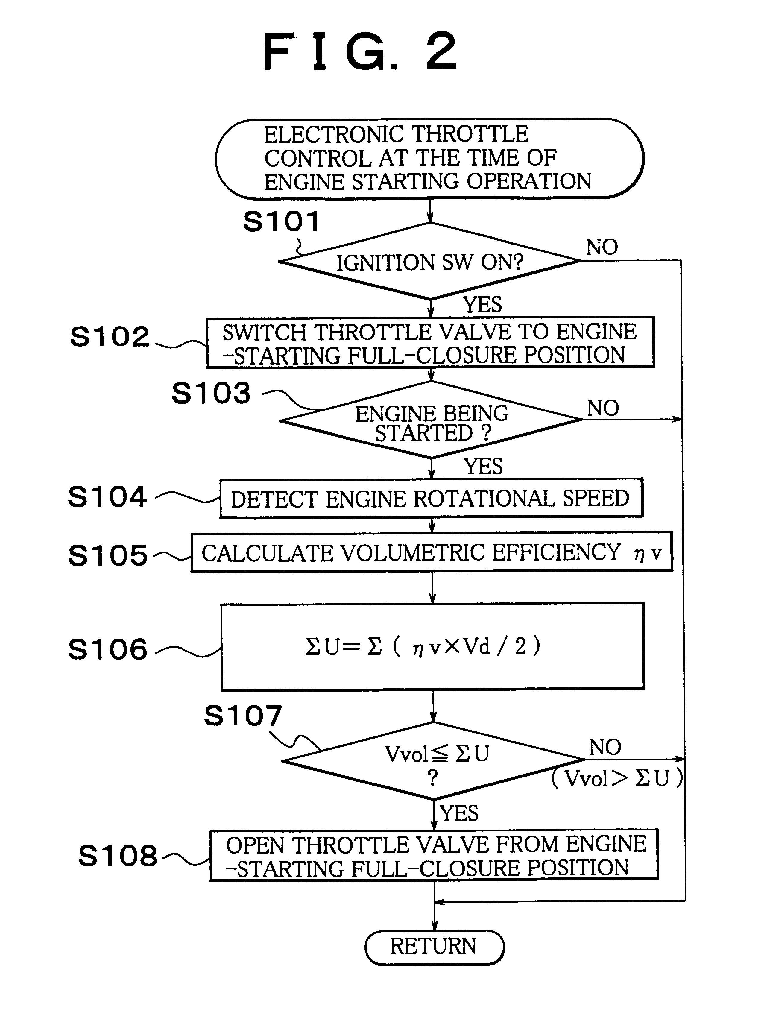
FIG. 2 is a flowchart showing a control procedure for opening the throttle valve 3 that has been completely closed since the starting of the engine 1. The routine shown in this flowchart is carried out at intervals of a predetermined length of time, for example, several milliseconds.
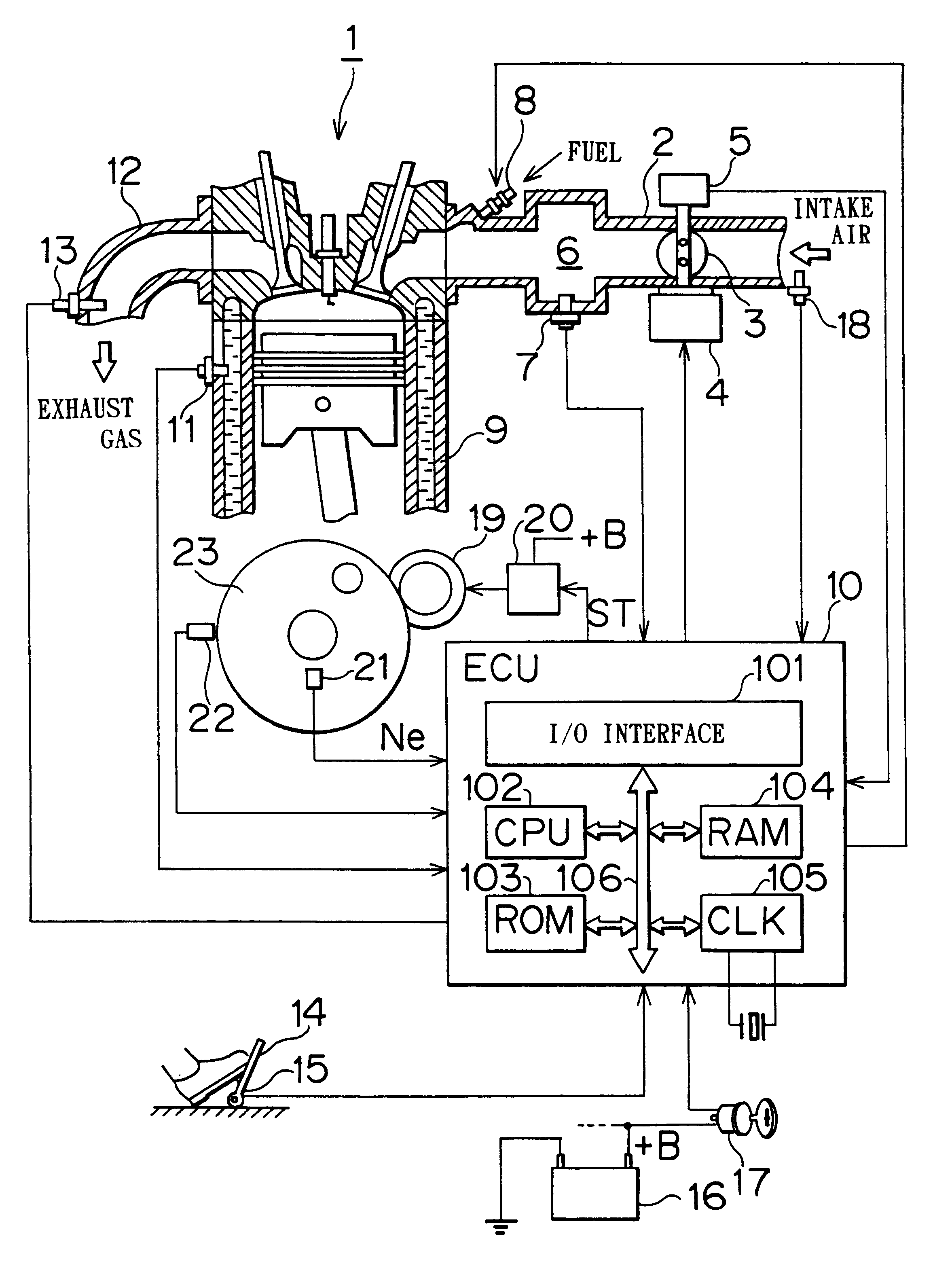
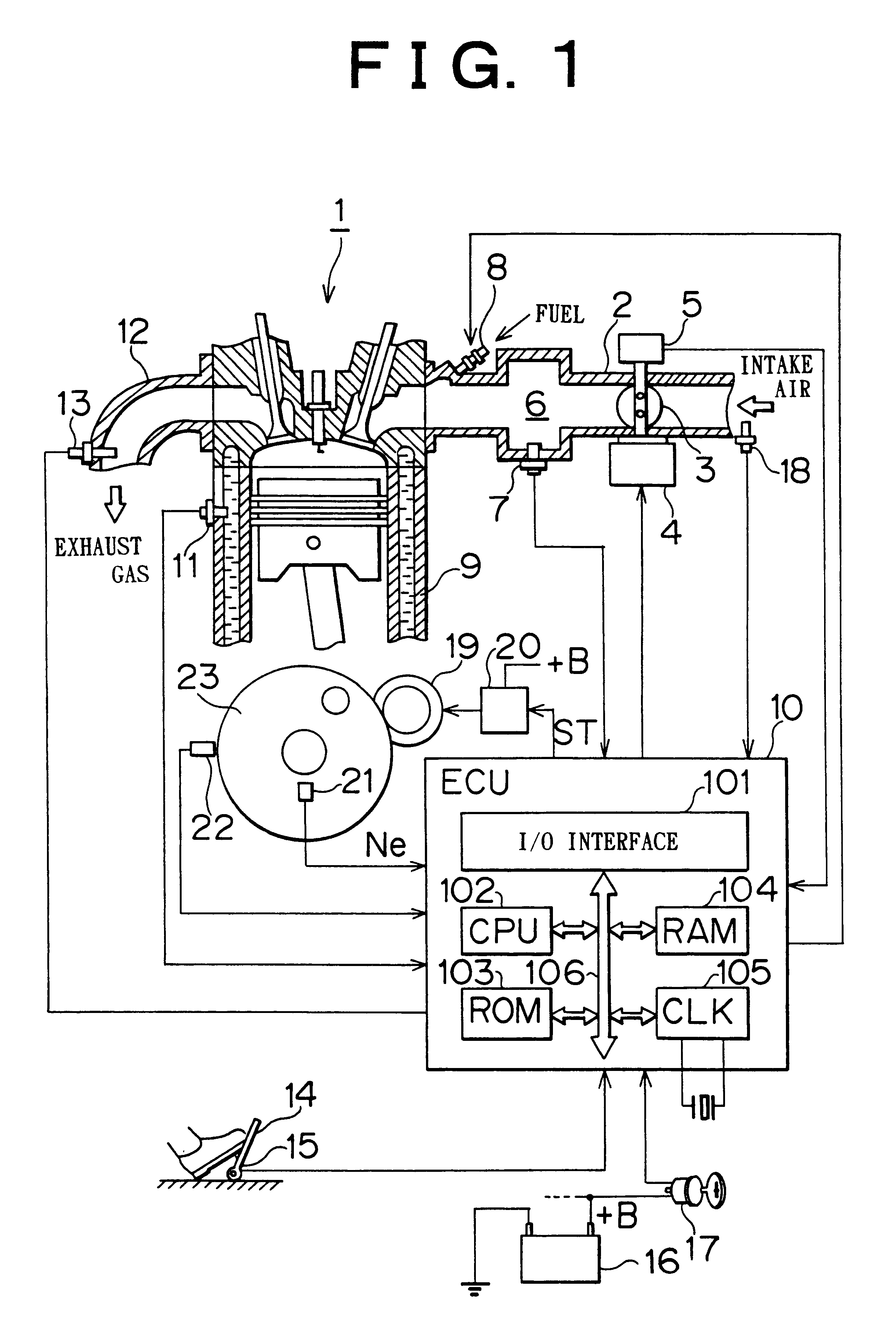
First of all, in step S101, it is determined whether or not the ignition switch 17 has been turned on, namely, whether or not an ON-signal has been inputted to the ECU 10 from the ignition switch 17. If the ignition switch 17 has not been turned on, the routine is terminated without performing any other processings. On the other hand, if it is determined that the ignition switch 17 has been turned on, the operation proceeds to step S102.
In step S102, the throttle motor 4 controls the throttle valve 3 such that the throttle valve 3 assumes its full-closure position at the time of engine starting operation. Then in step S103, it is detected whether or not the engine 1 is about to be started, namely, whethe...
second embodiment
FIG. 3 is a flowchart showing a control procedure for opening the throttle valve 3 that has been completely closed since the starting of the engine 1. The routine shown in this flowchart is also carried out at intervals of a predetermined length of time, for example, several milliseconds.
In the control of the second embodiment, control performed in case of a sudden drop in rotational speed of the engine 1 at the time of engine starting operation is added to the control procedure for opening the throttle valve 3 according to the first embodiment described with reference to FIG. 2. Accordingly, in the following description of the control procedure of the second embodiment, only what is different from the first embodiment will be described.
In the second embodiment, instead of step S104, a coolant temperature of the engine, which is regarded as a temperature of the engine, is detected together with an engine rotational speed in step S201.
In the first embodiment, if Vvol>.SIGMA.U (NO) in...
third embodiment
In the third embodiment, if the result is YES in step S103 (if the starter 19 is in operation), the operation proceeds to step S301.
In step S301, conditions concerning a volume of the engine 1 downstream of the throttle valve 3, a coolant temperature of the engine, a temperature of lubricating oil and an atmospheric pressure are read, and a holding time Tclose for holding the throttle valve completely closed is calculated according to those conditions. As shown in FIG. 8A, the higher the atmospheric pressure becomes, the longer the holding time Tclose is made. As shown in FIG. 8B, the higher the coolant temperature or the oil temperature becomes, the shorter the holding time Tclose is made. In the following step S302, an elapsed time .SIGMA.TM after the starting of the engine 1 is calculated.
In step S303, the elapsed time .SIGMA.TM after the starting of the engine 1 is compared with the holding time Tclose for holding the throttle valve 3 completely closed. If .SIGMA.TM
PUM
 Abstract
Description
Claims
Application Information