Multi-layered article

Inactive Publication Date: 2002-02-05
MITSUBISHI GAS CHEM CO INC
View PDF13 Cites 37 Cited by
  • Summary
  • Abstract
  • Description
  • Claims
  • Application Information

AI Technical Summary

Benefits of technology

It is an object of the present invention to provide a multi-layered article which is formed of at least two resins and has resin layers of these resins laminated, which has an excellent appearance and is free from the occurrence of interlayer separation (delamination), and which is structured such that the resin which is not to compose the outermost layer of t

Problems solved by technology

However, a container formed of a biaxially oriented thermoplastic polyester resin composed mainly of PET resin does not necessarily have complete performances.
That is, when the content to be filled in a container is a food which requires high gas barrier properties of the container, the container formed of PET resin is insufficient in gas barrier properties against oxygen gas and carbon dioxide gas, and therefore, the container formed of PET resin has a defect that the taste of the content is impaired.
A multi-layered container (bottle) formed by biaxially stretch-blow molding a parison having the three-layer structure of PET resin layer/MX nylon resin layer/PET resin layer or the five-layer structure of PET resin layer/MX nylon resin layer/PET resin layer/MX nylon resin layer/PET resin layer has a problem that it is liable to undergo interlayer separation (delamination) when an impact is exerted thereon or when a sharp change occurs in internal pressure after carbonate beverage is filled therein.
Further, when a multi-layered container (bottle) having an extremely bend portion is produced by a biaxially stretch-blow molding method, there is another problem that the bend portion is liabl

Method used


Image

  • Multi-layered article
  • Multi-layered article
  • Multi-layered article

Examples


Example

The same resins as those in Example 1 and the same injection molding apparatus as that in Example 1 were used for injection molding. Temperature conditions were set as shown in Table 1. Example 2 differs from Example 1 in the following point. Example 1 employed a simultaneous-injection molding method, while Example 2 employed an alternate-injection molding method.

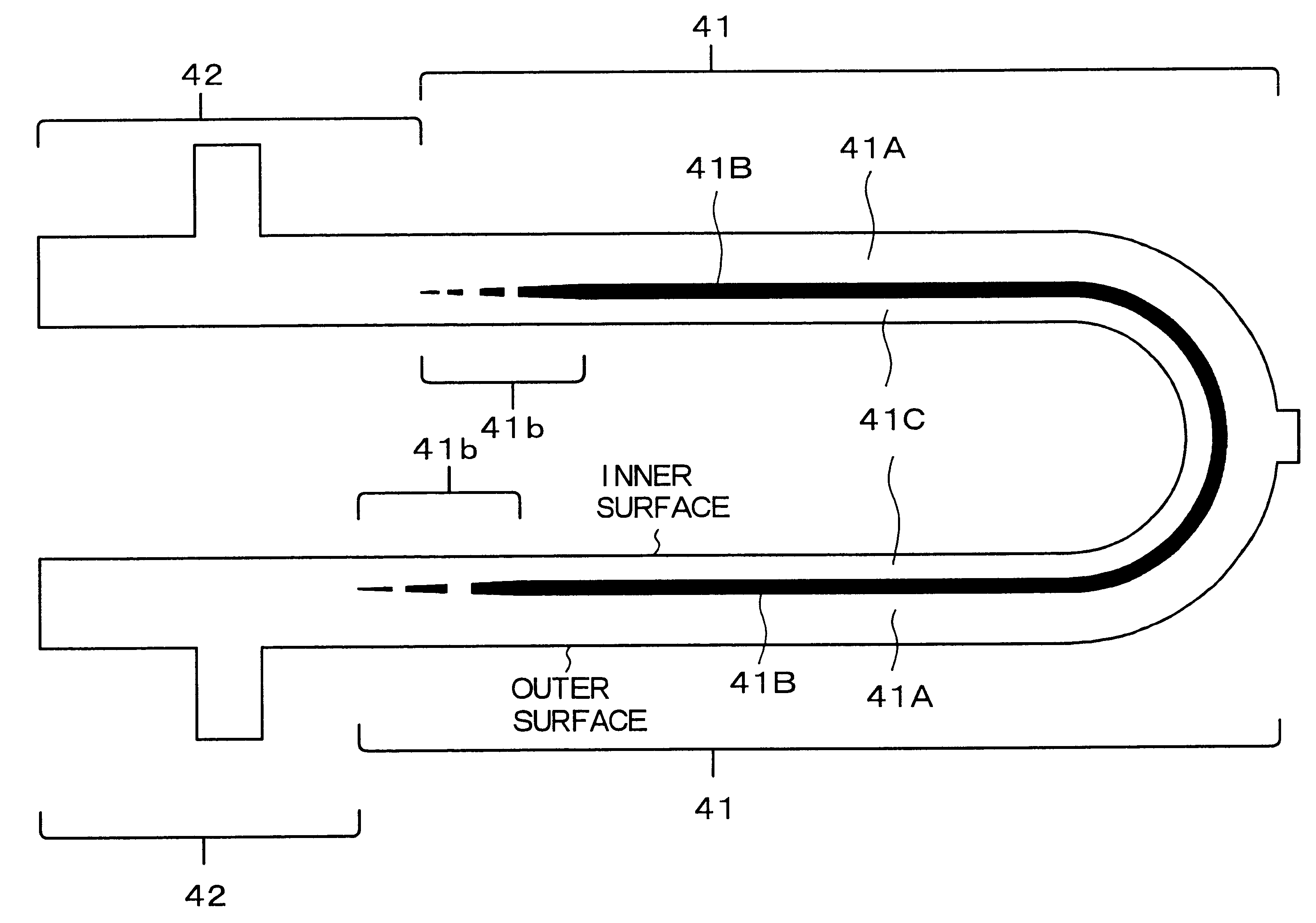
Before injection molding, the first molten resin 40A which flowed into the second resin-flow-passage 23B in a previous molding cycle (the total of the first molten resin 40a which was left in the second resin-flow-passage 23B and the first molten resin 40A which was to constitute the crudely-mixed-state resin portion 40b) was left in the second resin-flow-passage 23B in an amount equivalent to 15% of the volume of each cavity 25.

First, in the same manner as in [Step-100], the first molten resin 40A (molten PET resin) was injected into each cavity 25 in an amount equivalent to 40% of the volume of each cavity 25. In this ste...

Example

COMPARATIVE EXAMPLE 1

Parisons were molded in the same manner as in Example 1 (a simultaneous-injection molding method) using the same first and second resins and the same injection molding apparatus as those described in Example 1, except that the back flow means was replaced with a conventional ball check valve for preventing back flow of a molten resin.

First, the first molten resin 40A (molten PET resin) was injected into each cavity 25 in an amount equivalent to 20% of the volume of each cavity 25. No first molten resin flowed into the second resin-flow-passage 23B in a previous molding cycle. In this step, no first molten resin 40A flowed into the second resin-flow-passage 23B.

Then, while the injection of the first molten resin 40A (molten PET resin) into each cavity 25 was continued, the second molten resin 40B (molten N-MXD6 resin) was injected into each cavity 25 from the second injection cylinder 10B in an amount equivalent to 5% of the volume of each cavity 25.

Then, the inj...

Example

COMPARATIVE EXAMPLE 2

Parisons were molded in the same manner as in Example 2 (an alternate-injection molding method) using the same first and second resins and the same injection molding apparatus as those described in Example 1, except that the back flow means was replaced with a conventional ball check valve for preventing back flow of a molten resin.

First, in the same manner as in [Step-100], the first molten resin 40A (molten PET resin) was injected into each cavity 25 in an amount equivalent to 40% of the volume of each cavity 25. No first molten resin flowed into the second resin-flow-passage 23B in a previous molding cycle. In this step, no first molten resin 40A flowed into the second resin-flow-passage 23B.

Then, in the same manner as in [Step-100], the second molten resin 40B (molten N-MXD6 resin) was injected into each cavity 25 from the second injection cylinder 10B in an amount equivalent to 5% of the volume of each cavity 25.

Then, in the same manner as in [Step-120], th...


PUM

PropertyMeasurementUnit
Fractionaaaaaaaaaa
Fractionaaaaaaaaaa
Thicknessaaaaaaaaaa

Abstract

A multi-layered article having a first portion constituted of laminated three resin layers and a second portion extending from the first portion, the first portion being constituted mainly of consecutively laminated resin layers composed of a first resin layer formed of a first resin, a second resin layer formed mainly of a second resin and a third resin layer formed of the first resin, the second portion being constituted of resin layers extending from the first resin layer and the third resin layer which constitute the first portion, the first resin layer constituting the outer surface layer of the multi-layered article, the third resin layer constituting the inner surface layer of the multi-layered article which inner surface layer is opposed to said outer surface layer, the second resin layer being encapsulated with the first resin layer and the third resin layer, the second resin layer having a thickness which decreases towards the second portion, and being discontinued, in a region of the first portion in the vicinity of the second portion.

Description

1. Field of the InventionThe present invention relates to a multi-layered article such as a multi-layered container, a multi-layered parison which is a precursor of a multi-layered container, and a blow molded multi-layered container.2. Description of the Related ArtIn recent years, containers formed of thermoplastic resins are widely used as containers for cosmetics, foods, beverages and the like, from the viewpoints of light weight and safety for breaking. The development of containers formed of a polyethylene terephthalate resin (to be sometimes abbreviated as "PET resin" hereinafter) in particular is rapidly advancing owing to improvements in biaxial orientation blow molding technology. However, a container formed of a biaxially oriented thermoplastic polyester resin composed mainly of PET resin does not necessarily have complete performances. That is, when the content to be filled in a container is a food which requires high gas barrier properties of the container, the containe...

Claims


Application Information

Patent Timeline
IPC IPC(8): B29C45/16B29C45/26B32B1/02B29C45/76B29C49/06B29C49/22B32B27/36
CPCB29C45/1643B29C45/1646B29B2911/1402Y10T428/13B29B2911/1404B29B2911/14086B29B2911/14093B29B2911/1412B29B2911/14126B29B2911/14146B29B2911/14153B29B2911/14593B29B2911/14653B29B2911/14713B29C2045/1648B29K2105/253Y10T428/1379Y10T428/1383B29B2911/14026B29C2949/3018B29C2949/302B29C2949/28B29C2949/24B29C2949/22B29C2949/3028B29C2949/303B29C2949/3036B29C2949/3038B29C2949/0811B29C2949/082B29C2949/0829
Inventor MARUYAMA, KATSUYAHARA, TAKESHITERADA, YOSHIHIROOTA, TAKAO
Owner MITSUBISHI GAS CHEM CO INC
Why Eureka
Try Eureka