Direct-fuel-injection-type spark-ignition internal combustion engine and method of controlling the internal combustion engine

a technology of internal combustion engine and fuel injection type, which is applied in the direction of electric control, machines/engines, mechanical equipment, etc., can solve the problems of deteriorating fuel consumption rate, insufficient cooling of the upper section of the cylinder bore on the side opposed to the nozzle hole of the fuel injection valve, and inability to inject a large amount of fuel in the latter half of the compression strok

Inactive Publication Date: 2002-02-26
TOYOTA JIDOSHA KK
View PDF3 Cites 13 Cited by
  • Summary
  • Abstract
  • Description
  • Claims
  • Application Information

AI Technical Summary

Problems solved by technology

Thus, it is impossible to inject a large amount of fuel in the latter half of a compression stroke.
Because the entire cylinder bore has been cooled by coolant, this adherent fuel remains where it is without being sufficiently gasified, and thus does not contribute to combustion.
For this reason, there is caused a problem of deterioration of fuel consumption rate or a problem of dilu

Method used


Image

  • Direct-fuel-injection-type spark-ignition internal combustion engine and method of controlling the internal combustion engine
  • Direct-fuel-injection-type spark-ignition internal combustion engine and method of controlling the internal combustion engine
  • Direct-fuel-injection-type spark-ignition internal combustion engine and method of controlling the internal combustion engine

Examples


first embodiment

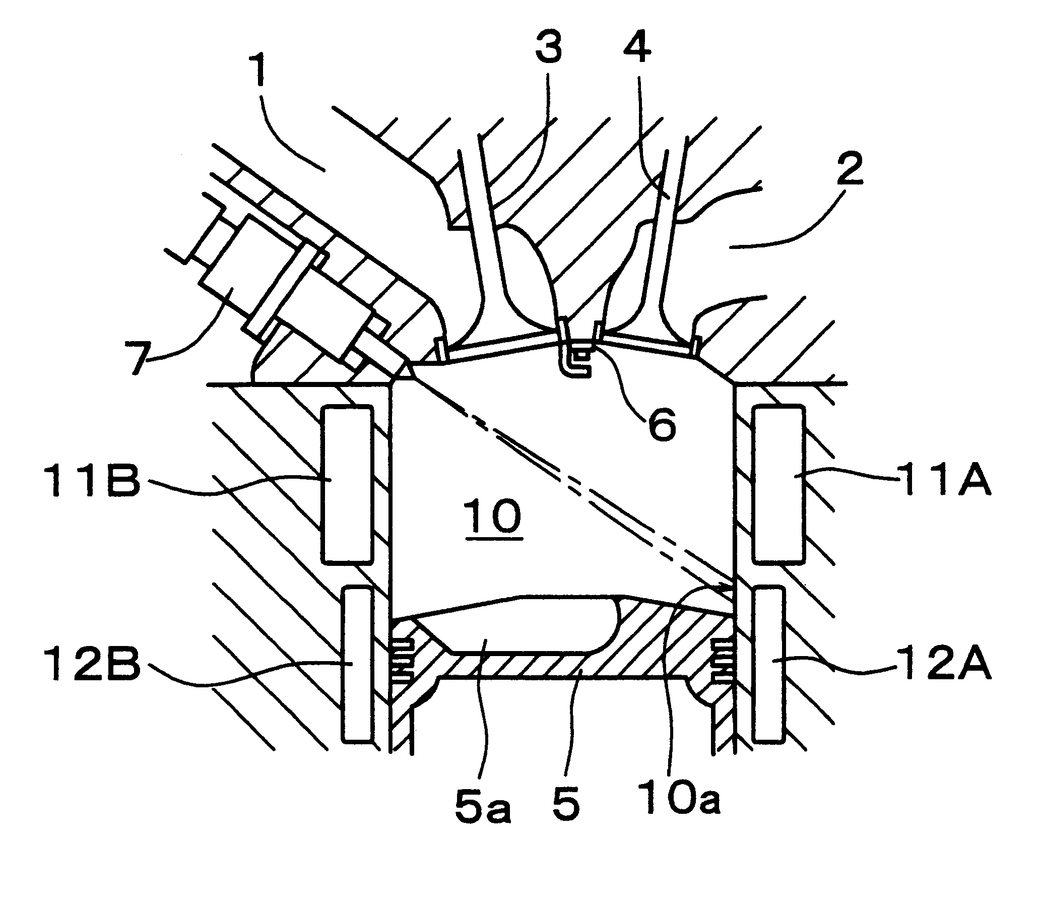
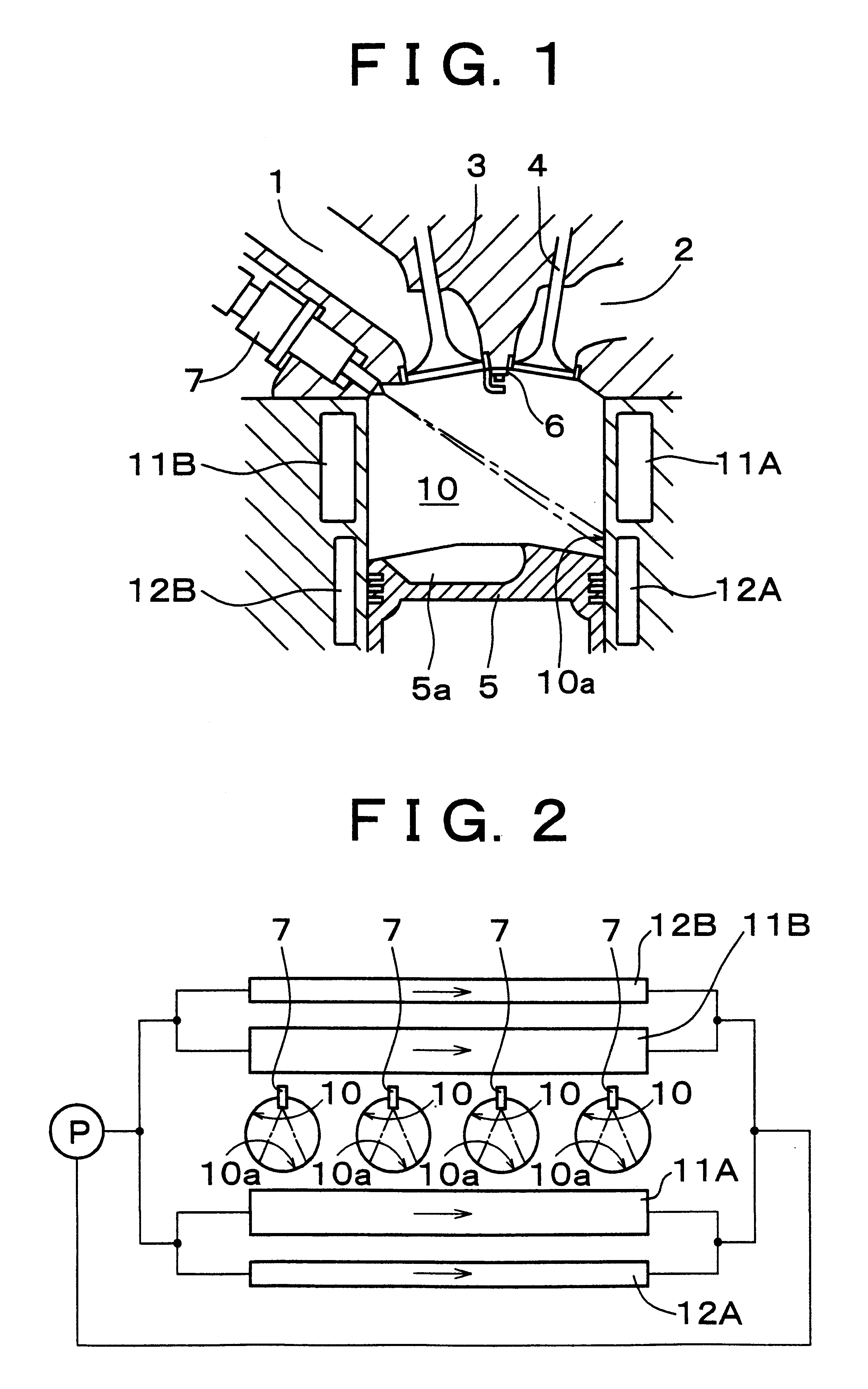
FIG. 1 schematically shows a longitudinal section of a direct-fuel-injection-type spark-ignition internal combustion engine in accordance with the present invention. In FIG. 1, an intake port 1 and an exhaust port 2 are disposed in an upper section of a cylinder. The intake port 1 leads to the cylinder through an intake valve 3, and the exhaust port 2 leads to the cylinder through an exhaust valve 4. A piston 5 is disposed in the cylinder, and a recessed cavity 5a is formed in a top face of the piston 5. An ignition plug 6 is disposed substantially at the center of an upper section of a combustion chamber. A fuel injection valve 7 for directly injecting fuel into the cylinder from the periphery of the upper section of the cylinder is disposed to circumvent the intake port 1 and the exhaust port 2. To avoid vaporization of fuel, the fuel injection valve 7 is disposed on the side of the intake valve which is at a relatively low temperature due to the flow of intake air. The fuel injec...

fifth embodiment

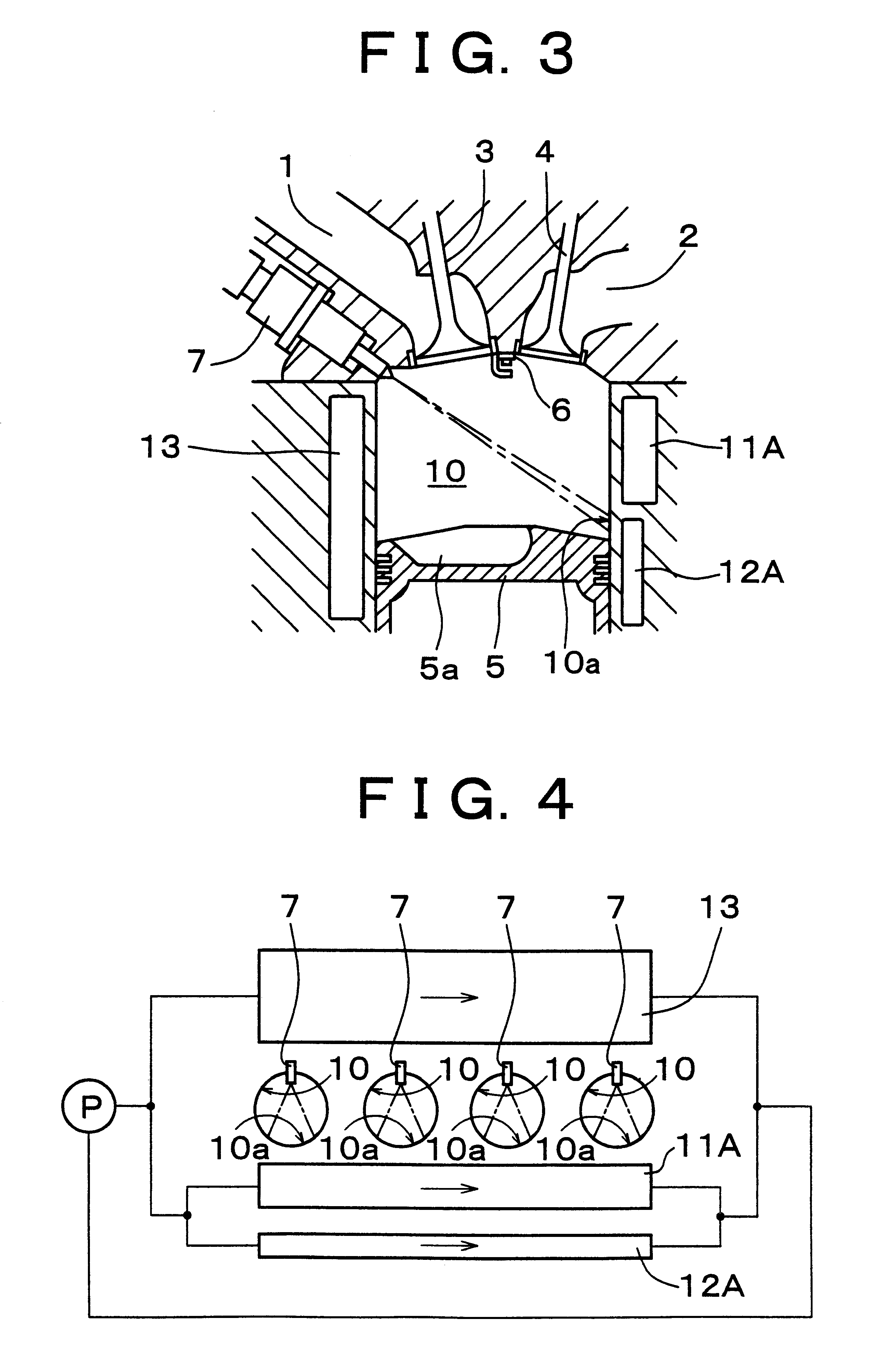
Thus, if an exhaust passage is formed in the neighborhood of the lower section of the cylinder bore 10 on the side opposed to the nozzle hole of the fuel injection valve, the impingement portion 10a opposed to the nozzle hole of the fuel injection valve in the lower section of the cylinder bore 10 can be heated by exhaust gas that has just been discharged from the cylinder and that is at a high temperature. Thus, the impingement portion 10a opposed to the nozzle hole of the fuel injection valve further rises in temperature and becomes capable of gasifying adherent fuel almost instantaneously. As a result, the fifth embodiment can more reliably solve the problems of deterioration of fuel consumption rate and dilution of engine oil.

fourth embodiment

The exhaust passage 15 may be designed as part of a main exhaust passage of the engine through which exhaust gas flows constantly. However, in this embodiment, the exhaust passage 15 is designed as a branch exhaust passage which branches off from a main exhaust passage 16 through a control valve 17, as can be seen from FIG. 10. At the time of stratified charge combustion, which does not require heating of the impingement portion 10a opposed to the nozzle hole of the fuel injection valve in the cylinder bore 10, the control valve 17 is closed so that exhaust gas does not flow through the branch exhaust passage 15. Thus, at the time of stratified charge combustion, the impingement portion 10a opposed to the nozzle hole of the fuel injection valve in the cylinder bore 10 is maintained at almost the same temperature as in the fourth embodiment wherein the adiabatic layer is formed.

As described above, regardless of whether stratified charge combustion or homogeneous combustion is carried...


PUM


Abstract

A direct-fuel-injection-type spark-ignition internal combustion engine has a fuel injection valve which directly injects fuel into a cylinder. A nozzle hole of the fuel injection valve directs fuel toward an impingement portion of the cylinder bore located opposed to the nozzle hole in a lower section of the cylinder bore so that fuel can be injected into a cavity formed in a top face of a piston from an upper section of the cylinder bore during the latter half of a compression stroke. A cooler located at least in the neighborhood of the impingement portion in the lower section of the cylinder bore has a lower cooling capacity than a cooler located in the neighborhood of the upper section of the cylinder bore. Thus, fuel injected during the latter half of an intake stroke that adheres to the cylinder bore can be effectively gasified.

Description

INCORPORATION BY REFERENCEThe disclosure of Japanese Patent Application No. HEI 11-222815 filed on Aug. 5, 1999 including the specification, drawings and abstract is incorporated herein by reference in its entirety.1. Field of the InventionThe invention relates to direct-fuel-injection-type spark-ignition internal combustion engines and to methods of controlling the internal combustion engine. More particularly, the invention relates to direct-fuel-injection-type spark-ignition internal combustion engines which effectively gasify fuel that has adhered to a cylinder bore and to methods of controlling the internal combustion engine.2. Description of Related ArtA direct-fuel-injection-type spark-ignition internal combustion engine has a fuel injection valve which directly injects fuel into a cylinder. In this engine, fuel injected into a cylinder in the latter half of a compression stroke is gasified, and a combustible mixture with good ignitability is formed only in the neighborhood o...

Claims


Application Information

Patent Timeline
IPC IPC(8): F02B17/00F02F1/42F02F3/26F01P3/02F01P7/16F02B75/12F02B75/00F01P7/14F01N13/08F02B23/10F02D41/02F02D41/04F02F1/10
CPCF02F3/26F02B17/005F01P7/165F01P2003/021F01P2003/027Y02T10/123F02B2075/125Y02T10/12
Inventor KANDA, MUTSUMISASAKI, CHIEMI
Owner TOYOTA JIDOSHA KK
Why Eureka
Try Eureka