Polymer electrolyte batteries having improved electrode/electrolyte interface

a technology of polymer electrolyte and electrode, which is applied in the direction of non-aqueous electrolyte cells, cell components, electrochemical generators, etc., can solve the problems of poor adhesion between the positive or negative electrode, leakage of non-aqueous electrolyte solution or degradation of battery characteristics, and increase of resistan

Inactive Publication Date: 2002-03-12
GK BRIDGE 1
View PDF9 Cites 47 Cited by
  • Summary
  • Abstract
  • Description
  • Claims
  • Application Information

AI Technical Summary

Benefits of technology

A second object of the invention is to enhance the ionic conductivity at the interface between the positive or negative electrode and the polymer electrolyte.
A third object of the invention is to improve the charge / discharge cycle characteristics of the polymer electrolyte battery.
As suggested by the polymer electrolyte battery of the invention, if the positive or negative electrode is formed with the inorganic amorphous solid electrolyte film at its interface with the polymer electrolyte, the adhesion between the polymer electrolyte and the positive or negative electrode is increased by this inorganic solid electrolyte film. In addition, the inorganic solid electrolyte film itself has the ionic conductivity. Hence, the resistance at the interface between the polymer electrolyte and the positive or negative electrode is decreased. As a result, the interface between the polymer electrolyte and the positive or negative electrode is improved in the ionic conductivity so that uniform cell reactions take place in repeated charge / discharge processes, leading to the improved charge / discharge cycle characteristics of the polymer electrolyte battery.
Any of the know materials generally used in the art may be employed as the aforesaid polymer. Examples of a suitable polymer include those having a molecular weight of 5000 to 500000 such as polyethylene glycol methacrylate, polyethylene oxide, polyethylene-imine, polyvinylidene fluoride, polyacrylonitrile and the like. In particular, the use of such a polymer as a polyethylene oxide and a polyethylene-imine results in an even greater improvement of the charge / discharge cycle characteristics of the polymer electrolyte battery. A conceivable reason for this is because the polymer comprised of a polyethylene oxide or a polyethylene-imine contributes to an even greater adhesion between the polymer electrolyte and the inorganic solid electrolyte film, thereby further reducting the resistance at the interface between the positive or negative electrode and the polymer electrolyte.

Problems solved by technology

Unfortunately, such a non-aqueous electrolyte battery suffers leakage of the non-aqueous electrolyte solution or degradation of the battery characteristics resulting from reaction between the non-aqueous electrolyte solution and the positive or negative electrode.
Unfortunately, however, the aforesaid polymer electrolyte batteries suffer such a poor adhesion between the positive or negative electrode and the polymer electrolyte that resistance is increased at the positive electrode / polymer electrolyte interface or the negative electrode / polymer electrolyte interface.
This detrimentally degrades the charge / discharge cycle characteristics of the polymer electrolyte batteries.
However, the addition of the surfactant to the polymer electrolyte involves a fear that the surfactant may form impurities responsible for the deterioration of a positive- or negative-electrode active material, thus conversely lowering the charge / discharge cycle characteristics of the polymer electrolyte battery.

Method used


Image

  • Polymer electrolyte batteries having improved electrode/electrolyte interface
  • Polymer electrolyte batteries having improved electrode/electrolyte interface
  • Polymer electrolyte batteries having improved electrode/electrolyte interface

Examples


example 2

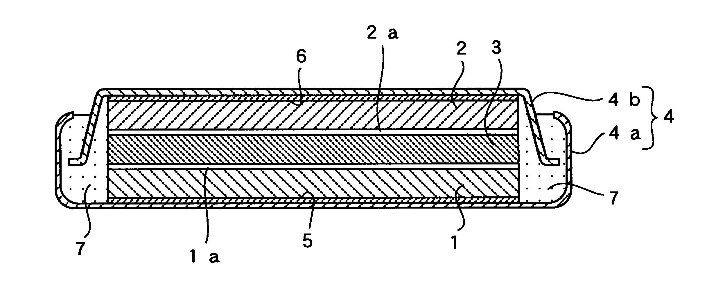
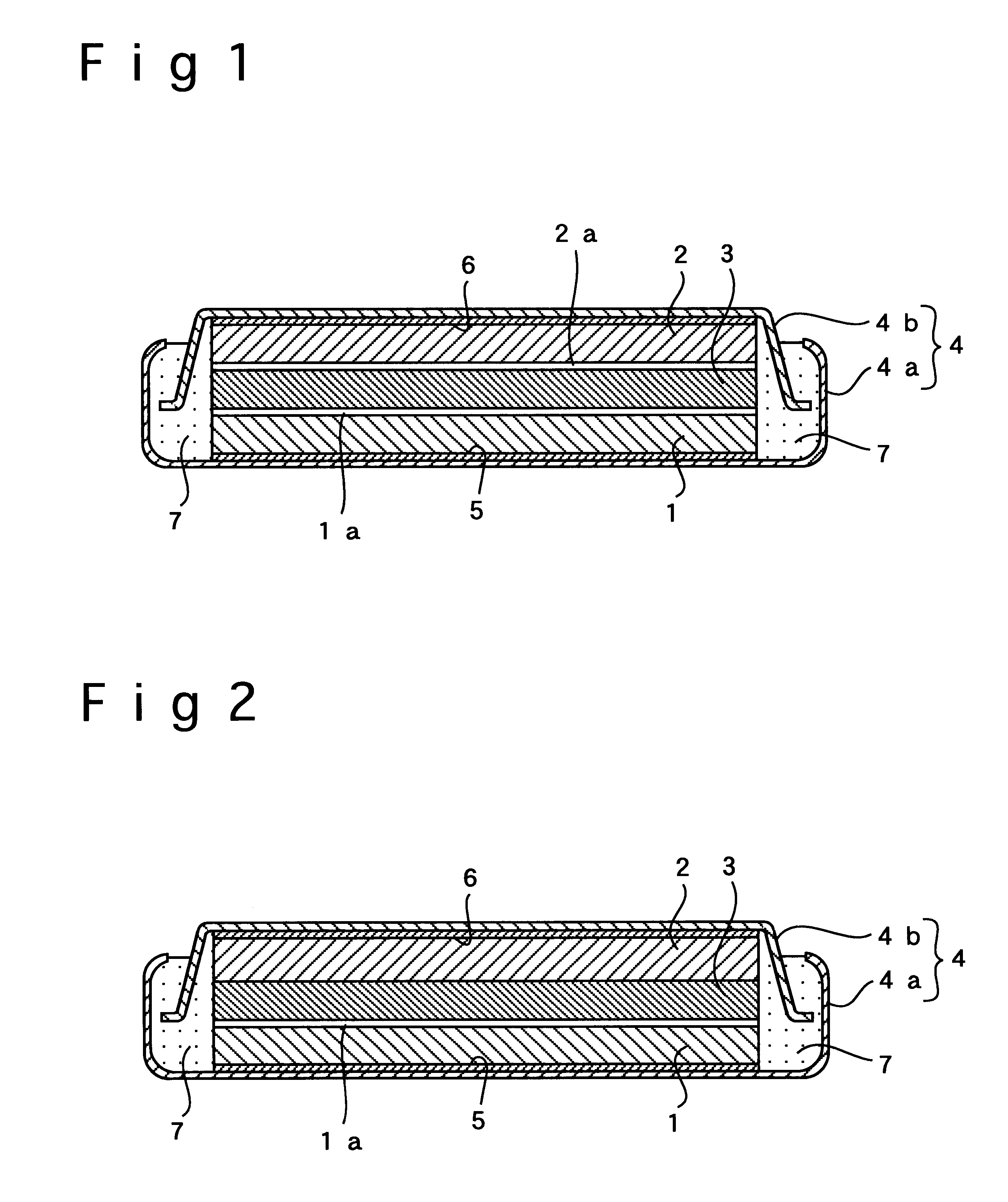
In Example 2, a flat-type polymer electrolyte battery was fabricated the same way as in Example 1 except that the negative electrode was free of the inorganic amorphous solid electrolyte film of LiTi.sub.2 (PO.sub.4).sub.3, which was placed at the interface between the negative electrode and the polymer electrolyte in Example 1. As shown in FIG. 2, the inorganic amorphous solid electrolyte film 1a of LiTi.sub.2 (PO.sub.4).sub.3 was interposed only between the positive electrode 1 and the polymer electrolyte 3.

example 3

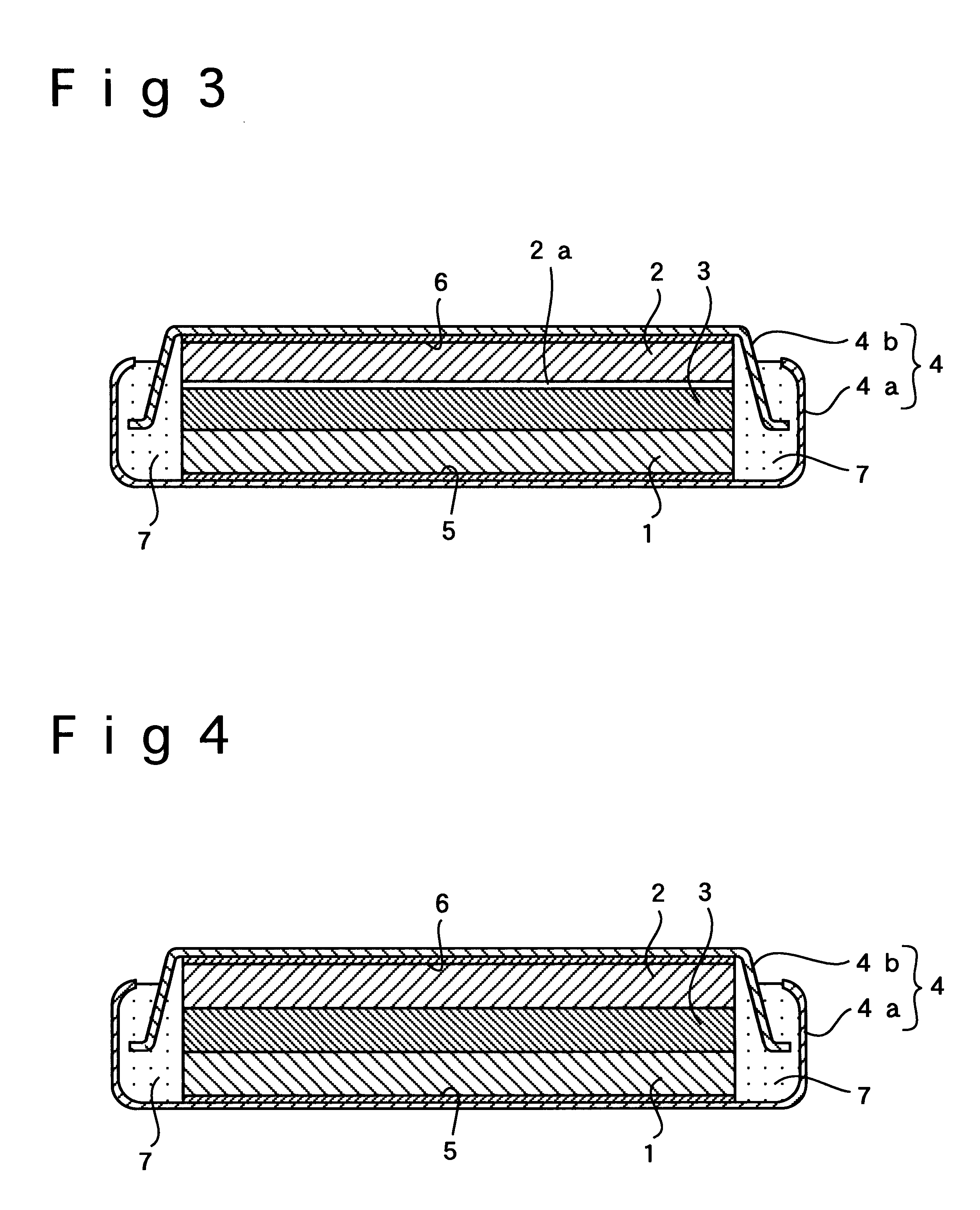
In Example 3, a flat-type polymer electrolyte battery was fabricated the same way as in Example 1 except that the positive electrode was free of the inorganic amorphous solid electrolyte film of LiTi.sub.2 (PO.sub.4).sub.3, which was placed at the interface between the positive electrode and the polymer electrolyte in Example 1. As shown in FIG. 3, the inorganic amorphous solid electrolyte film 2a of LiTi.sub.2 (PO.sub.4).sub.3 was interposed only between the negative electrode 2 and the polymer electrolyte 3.

examples 4 to 6

In Examples 4 to 6, a different material from that employed by Examples 1 to 3 was used for forming the inorganic amorphous solid electrolyte film at the interface between the polymer electrolyte and the positive or negative electrode. An inorganic amorphous solid electrolyte film was laid on the positive or negative electrode by sputtering using Li.sub.3 N as the target under the same conditions as in Example 1.

In Example 4, an inorganic amorphous solid electrolyte film of Li.sub.3 N was formed at the respective interfaces between the positive electrode and the polymer electrolyte and between the negative electrode and the polymer electrolyte in the aforementioned manner. Except for this, the same procedure as in Example 1 was taken to fabricate a flat-type polymer electrolyte battery wherein the inorganic amorphous solid electrolyte films 1a, 2a were interposed between the positive electrode 1 and the polymer electrolyte 3 and between the negative electrode 2 and the polymer elect...


PUM

PropertyMeasurementUnit
thicknessaaaaaaaaaa
thicknessaaaaaaaaaa
diameteraaaaaaaaaa

Abstract

In an inventive polymer electrolyte battery including a positive electrode, a negative electrode and a polymer electrolyte, at least one of the positive electrode and the negative electrode is formed with an inorganic amorphous solid electrolyte film at its interface with the polymer electrolyte.

Description

1. Field of the InventionThe present invention relates to a polymer electrolyte battery including a positive electrode, a negative electrode and a polymer electrolyte. More particularly, the invention relates to a polymer electrolyte battery with better charge / discharge cycle characteristics attained through improvement in the characteristics of a positive electrode / polymer electrolyte interface and a negative electrode / polymer electrolyte interface.2. Description of the Related ArtRecently, a non-aqueous electrolyte battery of high electromotive force based on the oxidation / reduction of lithium in the non-aqueous electrolyte solution has been used as one of novel batteries featuring high power and high energy density.Unfortunately, such a non-aqueous electrolyte battery suffers leakage of the non-aqueous electrolyte solution or degradation of the battery characteristics resulting from reaction between the non-aqueous electrolyte solution and the positive or negative electrode. In t...

Claims


Application Information

Patent Timeline
Patent Type & Authority Patents(United States)
IPC IPC(8): H01M10/36H01M10/40H01M2/16H01M6/18H01M4/13H01M4/133H01M10/052H01M10/0525H01M10/0562H01M10/0565
CPCH01M4/13H01M10/052H01M10/0562H01M10/0565H01M2/1673H01M4/133H01M6/185Y02E60/122H01M2300/0068H01M2300/0082H01M10/0525H01M50/46Y02E60/10
Inventor OHSHITA, RYUJIKAMINO, MARUONOHMA, TOSHIYUKINISHIO, KOJI
Owner GK BRIDGE 1
Why Eureka
Try Eureka