Lithium ion battery with electrolyte-embedded separator particles

Inactive Publication Date: 2013-02-28
GM GLOBAL TECH OPERATIONS LLC
View PDF5 Cites 70 Cited by
  • Summary
  • Abstract
  • Description
  • Claims
  • Application Information

AI Technical Summary

Benefits of technology

[0016]However, any electrically insulating particles substantial enough to support the loads applied to the electrodes will move rapidly through the electrolyte under the influence of gravity. So application of particles dispersed in a conventional electrolyte may be expected to produce a non-uniform particle distribution and leave at least some portion of the electrolyte deficient in particles. Any region of the electrode in contact with a particle-deficient region of the electrolyte will be more readily able to move into contact with the facing electrode when under mechanical load and initiate a short circuit.
[0017]This may be avoided by uniformly dispersing the particles in a much more viscous non-aqueous electrolyte, for example a gelled electrolyte. The viscosity of the gelled electrolyte is selected to prevent settling of the particles, but capable of being readily applied, in a layer of controlled thickness to one or other of the battery electrodes while maintaining suitable ionic conductivity. An electrolyte with a viscosity of about 100 centipoise (cP) suitably satisfies this requirement but electrolytes with viscosities as low as 30 cP may also be used. A gel may be laid down on a smooth surface as a layer of generally uniform thickness, using fo

Problems solved by technology

Lithium-ion secondary batteries are common in portable consumer electronics because of their high energy-to-weight ratios, lack of memory effect, and slow self-discharge when not in use.
In practice, however, less than 100% lithium re-intercalation occurs, leading to a progressive build-up of lithium and lithium containing reaction compounds on the anode surface during continued cycling.
These pores, which are necessary to provide a continuous electrolyte path for reversible transport of lithium ions during charging and discharging, require subjecting the polymer sheet to specialized processes and procedures, complicating the fabrication of such lithium-ion

Method used


Image

  • Lithium ion battery with electrolyte-embedded separator particles
  • Lithium ion battery with electrolyte-embedded separator particles
  • Lithium ion battery with electrolyte-embedded separator particles

Examples


Embodiment Construction

[0029]The following description of the embodiment(s) is merely exemplary in nature and is not intended to limit the invention, its application, or uses.

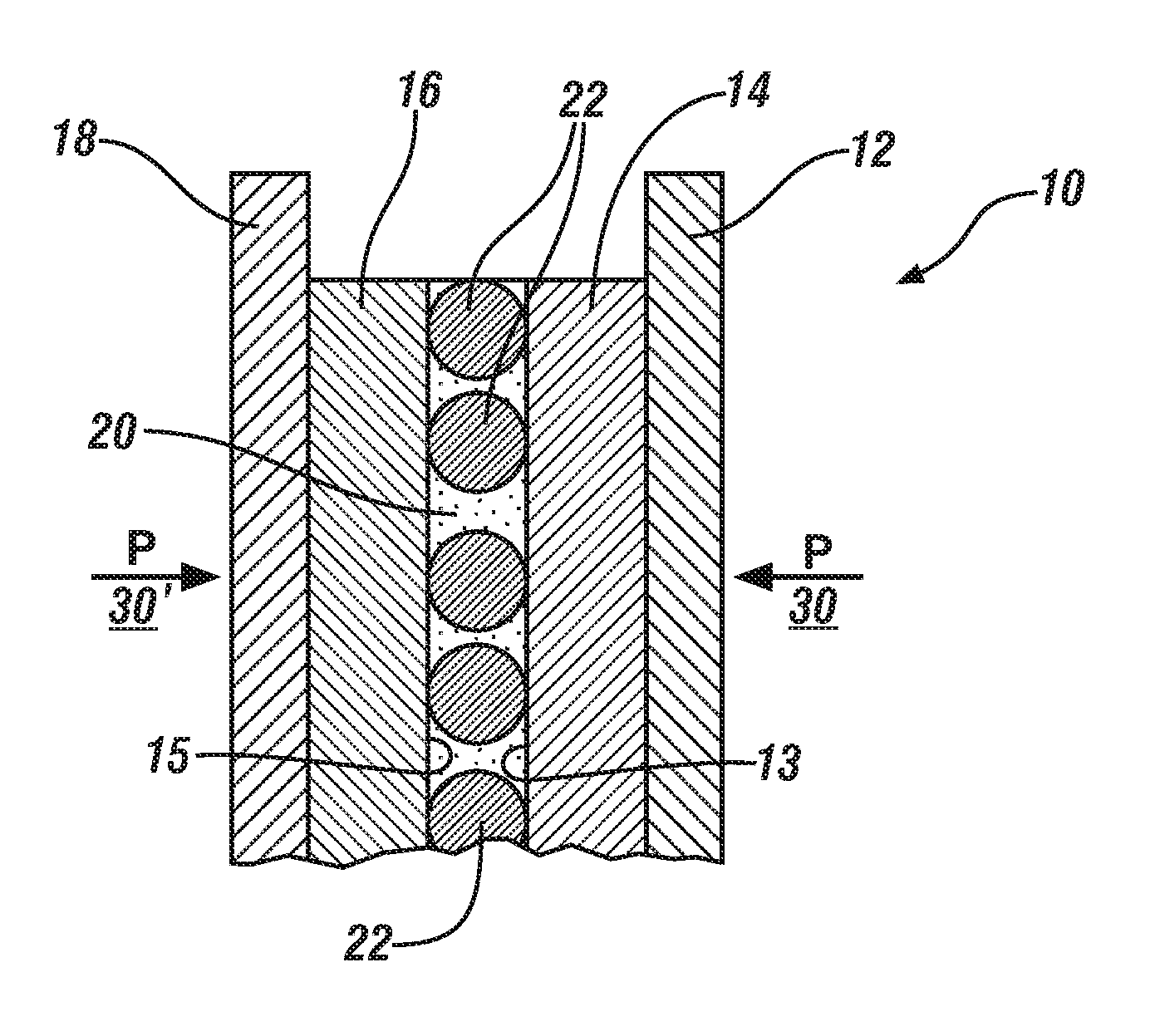
[0030]Conventional lithium-ion batteries employ a porous polymer interlayer or separator located between the anode and cathode of the cell to enforce separation of the electrodes and protect against internal short-circuits. Such separators, particularly at elevated temperatures may have limited resistance to penetration by electrically-conductive entities. Such entities may include fines or debris from battery manufacture, or lithium dendrites, lithium protrusions which form on the anode over some number of battery charge-discharge cycles and extend into the separator. If these electrically-conductive entities can span the full extent of the gap between electrodes a local short circuit will occur as these entities carry a very large current density and melt or vaporize to break the electrical connection and end the short circuit.

[003...


PUM

PropertyMeasurementUnit
Electrical conductivityaaaaaaaaaa
Viscosityaaaaaaaaaa

Abstract

A lithium ion battery in which electrically-non conducting ceramic particles are interposed between the anode and cathode to enforce separation between them and prevent short circuits is described. The particles, preferably equiaxed or monodisperse, may be generally uniformly dispersed in a non-aqueous gelled or high viscosity electrolyte. The electrolyte may be applied to one or both of the anode and cathode in suitable thickness to deposit the particles with the electrolyte and form a layered composite with substantially uniformly spaced particles suitable for holding the opposing anode and cathode faces in spaced-apart relation. The thickness of the applied electrolyte layer will be selected to enable deposition of the particles substantially as a fractional monolayer, a monolayer, or a multilayer as required for the application.

Description

TECHNICAL FIELD[0001]This invention pertains to methods of preventing internal short circuits between facing electrode layers of cells of a lithium-ion battery using ceramic particles in a non-aqueous ionic electrolyte.BACKGROUND OF THE INVENTION[0002]Lithium-ion secondary batteries are common in portable consumer electronics because of their high energy-to-weight ratios, lack of memory effect, and slow self-discharge when not in use. Rechargeable lithium-ion batteries are also being designed and manufactured for use in automotive applications to provide energy for electric motors to drive vehicle wheels.[0003]The basic unit of a lithium-ion battery is an individual cell which includes a facing anode and cathode in spaced-apart relation, and, between them, a non-aqueous liquid electrolyte suitable for carrying and conveying lithium ions. Lithium-ion batteries of different sizes, shapes and electrical capabilities may be fabricated by arranging any suitable number of these cells in p...

Claims


Application Information

Patent Timeline
IPC IPC(8): H01M2/16H01M10/04H01M2/18H01M50/403H01M50/586
CPCH01M2/145H01M2/34H01M10/052H01M10/0565H01M10/0567H01M10/0568Y10T29/49115H01M10/0585H01M10/4235H01M2300/0091Y02T10/7011Y10T29/49108H01M10/0569Y02E60/10H01M50/403Y02P70/50H01M50/586
Inventor HALALAY, ION C.JORGENSEN, SCOTT W.
Owner GM GLOBAL TECH OPERATIONS LLC
Why Eureka
Try Eureka