Power generation system and method
- Summary
- Abstract
- Description
- Claims
- Application Information
AI Technical Summary
Benefits of technology
Problems solved by technology
Method used
Image

Examples
Embodiment Construction
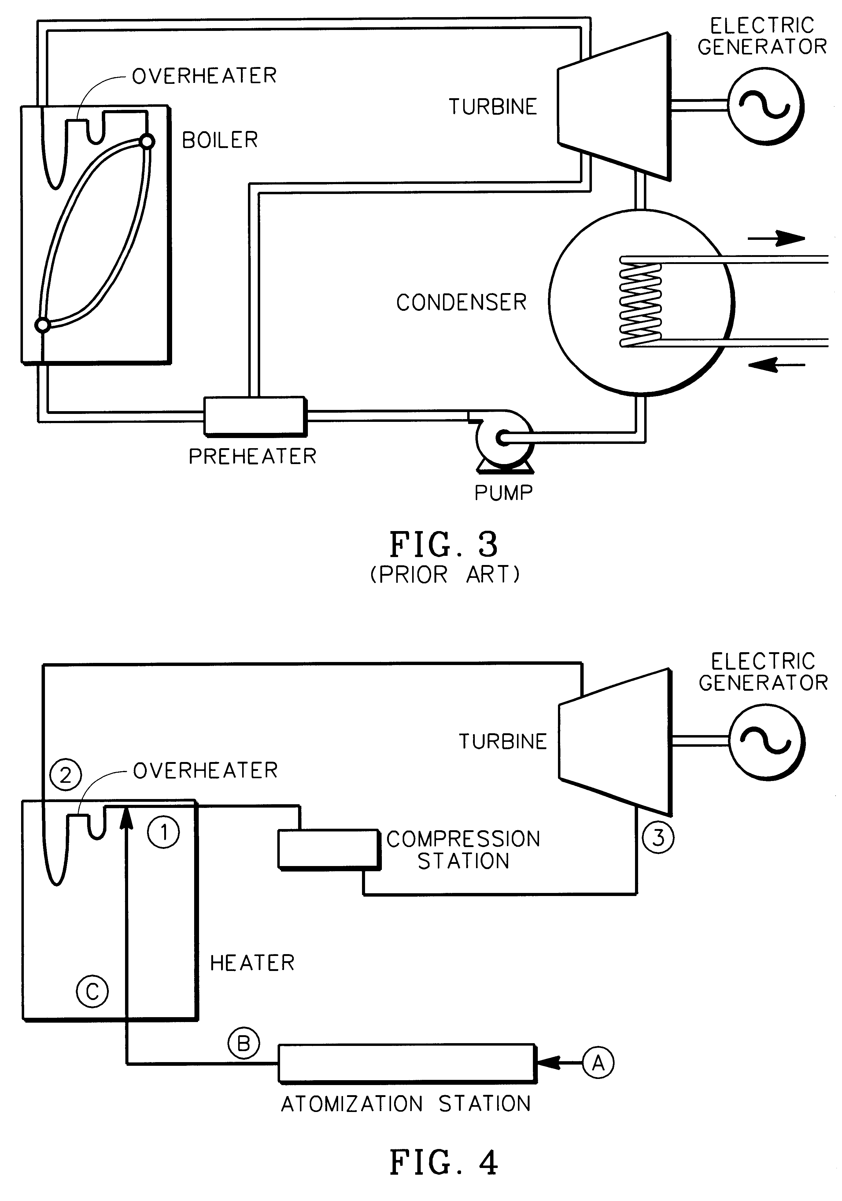
FIGS. 4 and 5 illustrates a power generation cycle, more particularly a steam power plant schematic and a pressure-versus-volume plot, respectively, according to a preferred embodiment of the present invention. The power generation cycle may be broken down into two processes; a first process characterized by reference points A-B-C-1, and second process characterized by reference points 1-2-3.
A-B-C-1 Process
The working fluid, in the form of feedwater, is introduced to the system at reference point A having a pressure P2 and a temperature T1. The feedwater is initially compressed in an atomizing station (seen in FIG. 4) under adiabatic conditions, resulting in a pressure P3 at temperature T1, as indicated at point B in FIG. 5. The water at condition B is then injected from the atomizing station into a heater, resulting in a slight expansion of the water at constant temperature to achieve pressure P4 and temperature T1, as indicated at reference point C in FIG. 5.
The heater receives th...
PUM
 Abstract
Description
Claims
Application Information
 - Generate Ideas
- Intellectual Property
- Life Sciences
- Materials
- Tech Scout
- Unparalleled Data Quality
- Higher Quality Content
- 60% Fewer Hallucinations
Browse by: Latest US Patents, China's latest patents, Technical Efficacy Thesaurus, Application Domain, Technology Topic, Popular Technical Reports.
© 2025 PatSnap. All rights reserved.Legal|Privacy policy|Modern Slavery Act Transparency Statement|Sitemap|About US| Contact US: help@patsnap.com