Control apparatus for hybrid vehicle

a control apparatus and hybrid technology, applied in the direction of hybrid vehicles, process and machine control, instruments, etc., can solve the problems of poor responsiveness to changing the transmission ratio, inferior acceleration response when a kick down is performed, and the driver unduly depresses the accelerator pedal, etc., to achieve smooth driving

Inactive Publication Date: 2002-03-19
HONDA MOTOR CO LTD
View PDF3 Cites 77 Cited by
  • Summary
  • Abstract
  • Description
  • Claims
  • Application Information

AI Technical Summary

Benefits of technology

According to this control method, if the responsiveness in changing the transmission ratio of the transmission is poor and the torque generated by the e

Problems solved by technology

However, in vehicles comprising continuously variable transmissions, the responsiveness in changing the transmission ratio is not good, there is the problem that the acceleration response when a kick down is performed is inferior to that of vehicles comprising stage transmissions.
Furthermore, because the acceleration response is not good due to the response delay in changing the transmission ratio, there is a tendency that the driver unduly depresses the accelerator pedal during the delay in the acceleration response, and that the throttle is opened wider than the driver wishes.
In such cases, there arise the problems that fuel consumption is increased, exhaust gas is increased, and noise and vibration are increased.
The above problems are common to hybrid vehicles comprising continuously variable transmissions.
That is, hybrid vehicles can enter into a running mode in which the vehicle is driven by the engine, and when in such a running mode using the engine, the problems due to the inferior responsiveness in changing the transmission ratio occur, similarly to those of conventional vehicles.
Also, when the running mode of a hybrid vehicle is shifted from a running mode in which the vehicle is driven by an electric motor to a running mode in which the vehicle is driven by an

Method used


Image

  • Control apparatus for hybrid vehicle
  • Control apparatus for hybrid vehicle
  • Control apparatus for hybrid vehicle

Examples


second embodiment

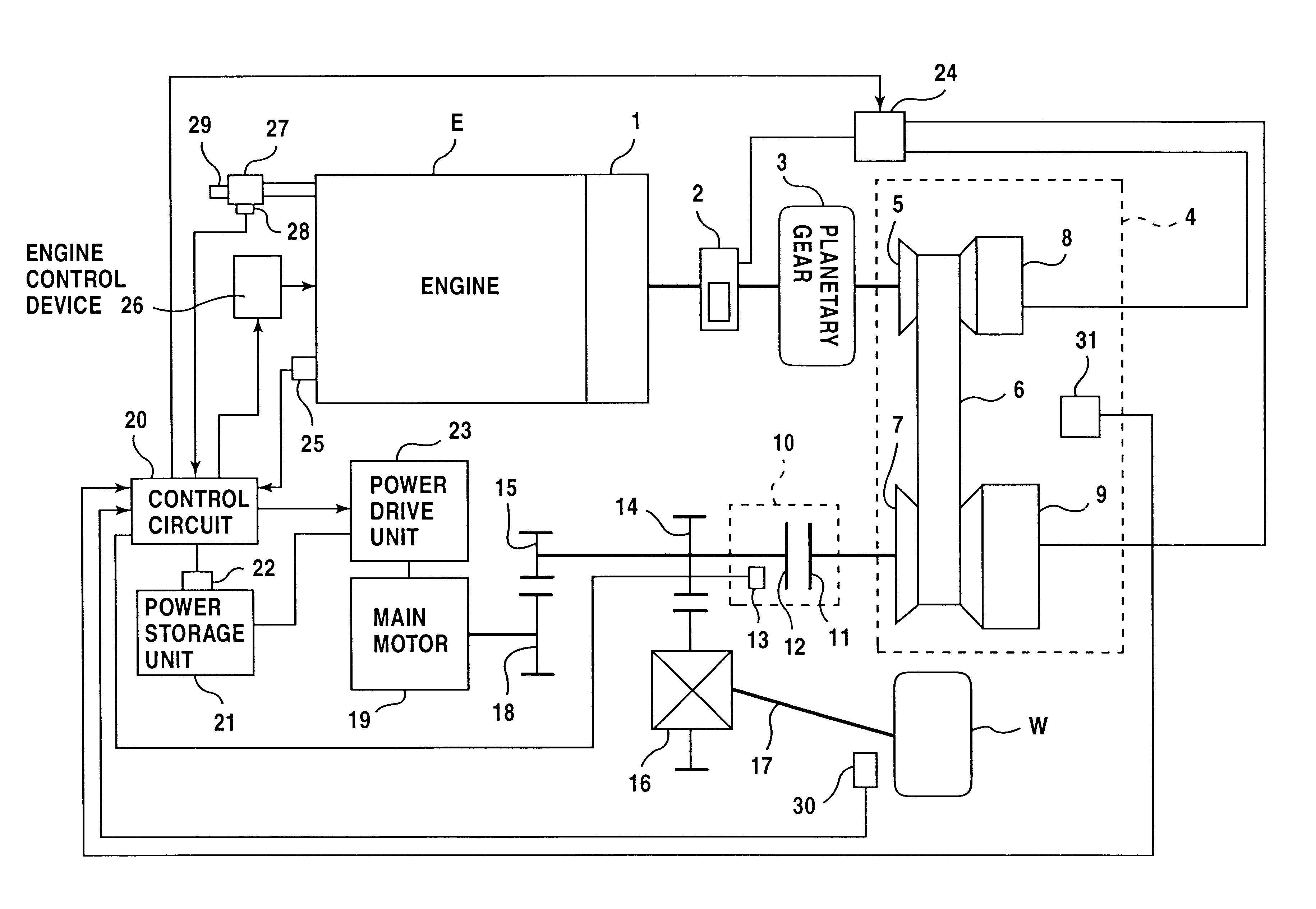
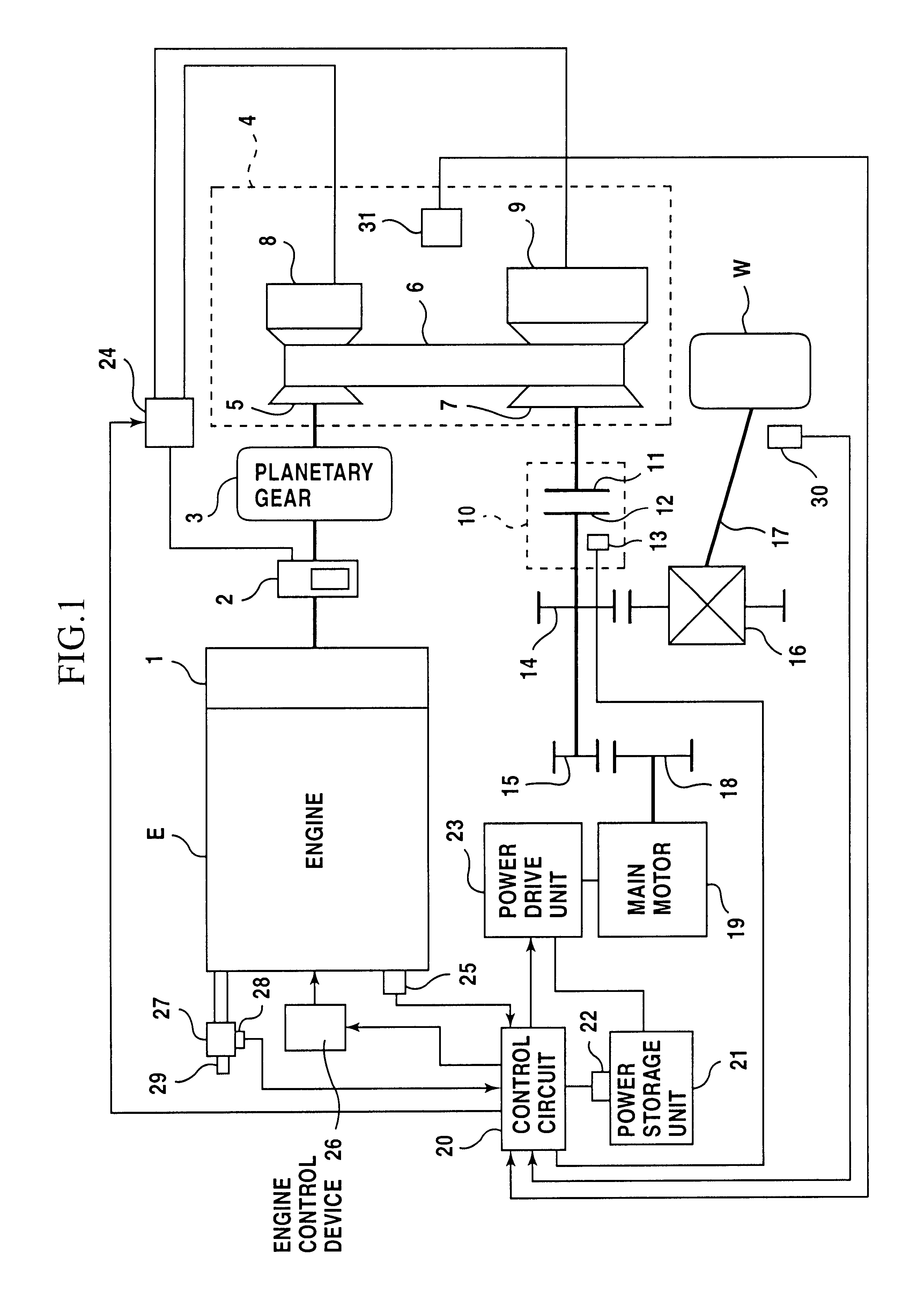
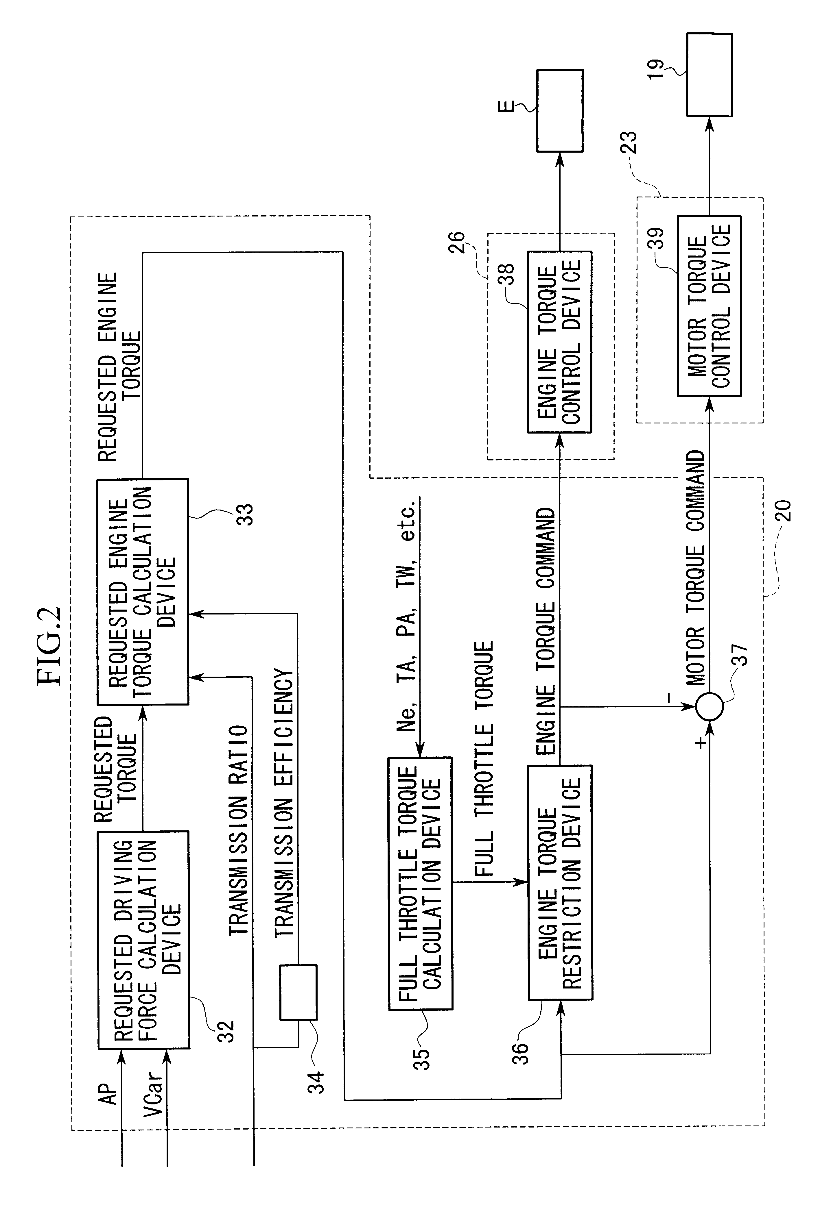
FIG. 5 is a timing chart illustrating the operation of the control circuit 20 of the second embodiment shown in FIG. 3. The operation in this embodiment is similar to that shown in FIG. 4; however, this operation is different from that of FIG. 4 in that the requested engine torque is restricted based on the engine torque limit. The deficiency in torque obtained by subtracting the engine torque limit from the requested engine torque is supplied as the motor torque.

third embodiment

Next, referring to FIG. 6, a third embodiment of the present invention will be explained. FIG. 6 is a block diagram illustrating a control circuit 20 of the third embodiment, and in this figure, the elements corresponding to the elements shown in FIG. 2 have the same reference numbers, and the explanation thereof will be omitted.

This control circuit 20 is different from that of FIG. 2 in that a motor torque command output device 37a is provided instead of the difference calculation device 37 shown in FIG. 2. The motor torque command output device 37a comprises an engine torque conversion device 40, a difference calculation device 41, and a motor torque conversion device 42.

The engine torque conversion device 40 receives the engine torque command output by the engine torque restriction device 36, the transmission ratio of the CVT 4 input from the outside of the control circuit 20, and the transmission efficiency output by the transmission efficiency calculation device 34, and outputs...

fourth embodiment

Next, referring to FIG. 7, a fourth embodiment of the present invention will be explained. The fourth embodiment is a modification of the second embodiment shown in FIG. 3, and FIG. 7 is a block diagram illustrating a control circuit 20 of the fourth embodiment. In FIG. 7, the elements corresponding to the elements shown in FIG. 3 have the same reference numbers, and the explanation thereof will be omitted.

This control circuit 20 is different from that of FIG. 3 in that the motor torque command output device 37a which is the same as that of the third embodiment shown in FIG. 6 is provided in place of the difference calculation device 37 shown in FIG. 3.

According to the fourth embodiment, similarly to the third embodiment, the motor torque command output device 37a calculates the difference between the torque values converted to values at the most downstream point of the torque transmission passage, and further converts the calculated difference to the torque value at the most upstre...


PUM


Abstract

A control apparatus including a requestedtorque calculating device which calculates a torque requested for driving the hybrid vehicle; and a torque control device which controls a torque generated by an engine and a torque generated by an electric motor of the hybrid vehicle based on the requested torque calculated by the requested torque calculating device. The torque control device controls the electric motor so as to generate a torque obtained by subtracting a torque to be generated by the engine from the requested torque. Acoording to this control apparatus, if the responsiveness in changing the transmission ratio of the transmission is poor and the torque generated by the engine becomes lower than therequested torque, the electric motor is controlled to generate the deficient (supplementary) torque, and smooth acceleration of the vehicle can be performed.

Description

1. Field of the InventionThe present invention relates to a control apparatus for a parallel hybrid vehicle which uses an engine and a motor for driving the vehicle. In particular, the present invention relates to a control technique for transmitting the output of an engine to driving wheels using a CVT (Continuously Variable Transmission) in a parallel hybrid vehicle.2. Description of the Related ArtIn conventional (non-hybrid) vehicles comprising engines and continuously variable transmissions, by means of detecting the amount of depression of an accelerator pedal using a throttle opening sensor, the driving force required by the drivers of the vehicles is calculated, and based on the calculation results, the engine speed and the transmission ratio are selected to smoothly drive the vehicle.In comparison with vehicles comprising stage transmissions, because vehicles comprising continuously variable transmissions can select the optimum transmission ratio according to the condition ...

Claims


Application Information

Patent Timeline
IPC IPC(8): B60K6/00B60K6/04B60K6/20F02D29/02B60K6/48B60K6/543B60L50/16B60W10/06B60W10/08B60W10/26B60W20/00
CPCB60K6/48B60W10/06B60W10/08B60W20/00B60K6/543Y02T10/626B60L2240/423B60L2240/445B60L2240/486B60W2510/068B60W2510/244B60W2710/0666B60W2710/083B60W2710/105Y02T10/6221Y02T10/6286Y10S903/903Y10S903/918Y02T10/642B60K2006/4808Y02T10/62Y02T10/64B60W20/19B60W20/10B60W2510/0657B60W2510/0676
Inventor SUGIYAMA, TETSUASAMI, KIYOSHISHIMABUKURO, EIJIRO
Owner HONDA MOTOR CO LTD
Why Eureka
Try Eureka