Apparatus and method for positioning an engine throttle

a technology of engine throttle and apparatus, applied in the field of new, can solve the problems of increasing load, routine engine load change, and increasing load often kill the engine, and achieve the effect of increasing the engine speed

Inactive Publication Date: 2002-04-02
GENERAC POWER SYSTEMS
View PDF21 Cites 21 Cited by
  • Summary
  • Abstract
  • Description
  • Claims
  • Application Information

AI Technical Summary

Benefits of technology

The improvement comprises a governor apparatus including a linkage arm coupled to the throttle valve, a spring applying a vector force to the linkage arm and a motor mounted with respect to the engine for changing the angle of the vector force with respect to the linkage arm. The motor causes the included angle to increase when the current increases, thereby increasing the speed of the engine.
In a highly preferred embodiment of the combination, the go

Problems solved by technology

But in applications like those described above, engine load routinely changes.
For example, a lawn mower encounters grass of differing height or density and the resulting changing load causes engine speed to change.
But the resulting increased load

Method used


Image

  • Apparatus and method for positioning an engine throttle
  • Apparatus and method for positioning an engine throttle
  • Apparatus and method for positioning an engine throttle

Examples


Embodiment Construction

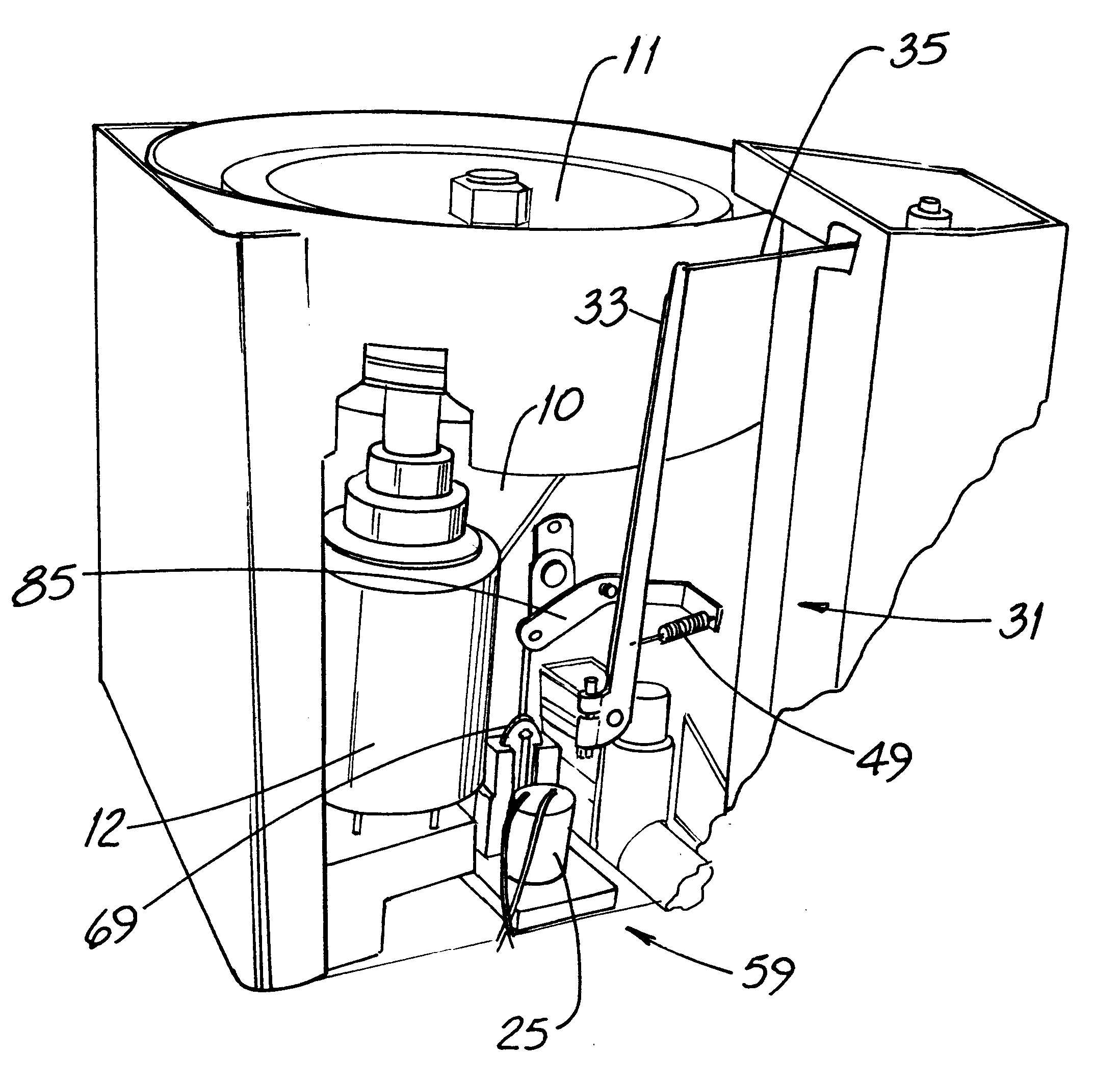
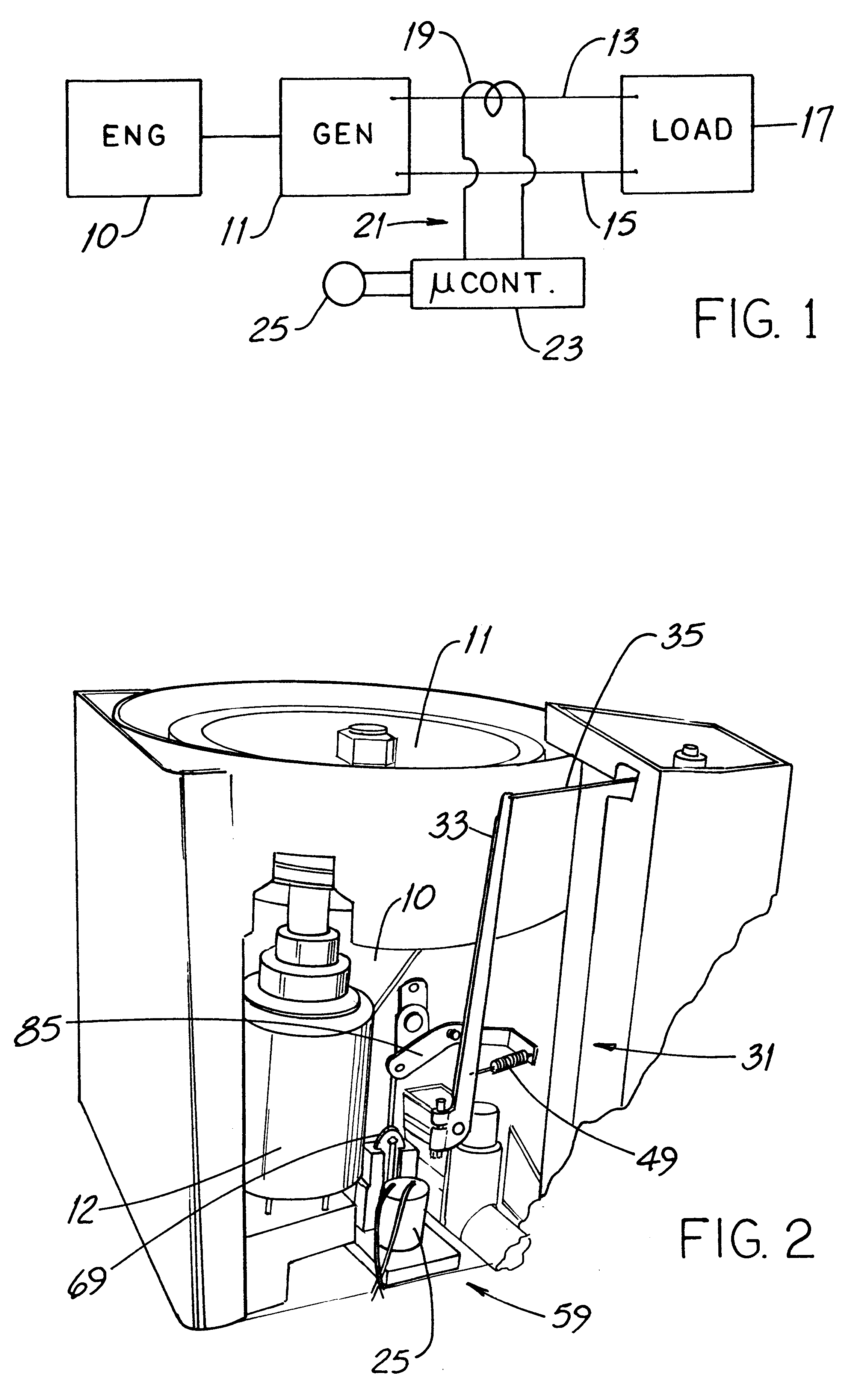
Referring first to FIG. 1 and 2, an internal combustion engine 10 is mechanically coupled to and drives an AC generator 11. The engine starter 12 is shown in FIG. 2. Two conductors 13, 15 are connected between the generator output terminals and a load 17 and a current transformer 19 is around one of the conductors 13. The electrical signal on the transformer lines 21 is proportional to the current flowing in the conductors 13, 15 and the frequency of the current can also be ascertained from such signal. The lines 21 are coupled to a microcontroller 23 which, in turn, is coupled to a positioning motor 25 described in more detail below.

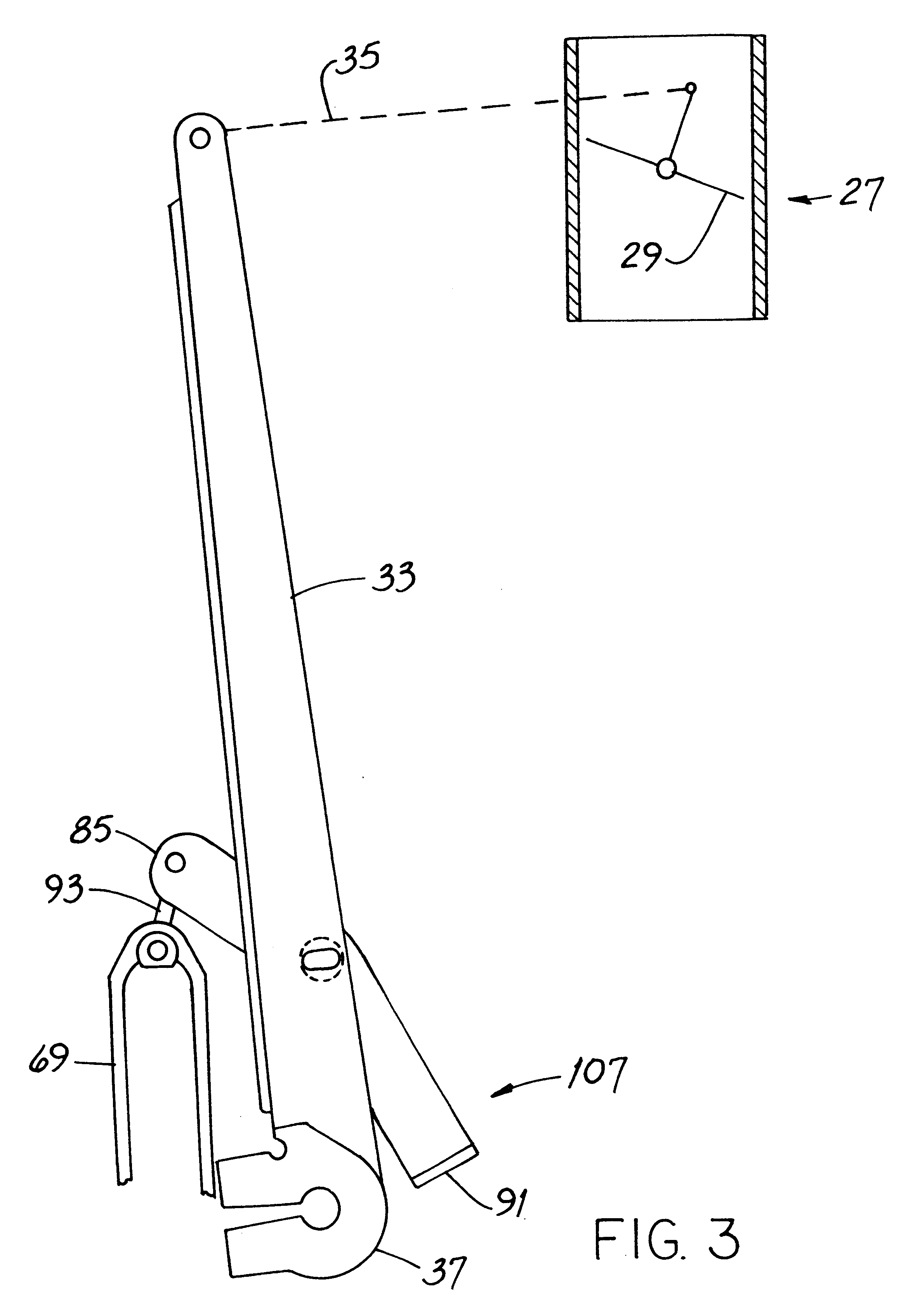
Referring also to FIGS. 3, 4 and 5, the engine 10 includes a fueling mechanism 27, e.g., a carburetor, with a butterfly-type throttle valve 29 which controls the rate of flow of air / fuel mixture to engine 10. When valve 29 is in the position shown in FIG. 3, engine 10 runs at low speed, and when valve 29 is in the position shown in FIG. 4, engine 10 run...


PUM


Abstract

A method for controlling the speed of an engine driving a generator supplying electrical current to a load includes the steps of monitoring the current, increasing the speed when the current increases and decreasing the speed when the current decreases. The governor apparatus used to carry out the method includes a microcontroller having a current and frequency look-up table embedded in it. For some part of the monitoring step, the engine runs at a first speed, e.g., idle speed, or some moderate speed above idle speed. The increasing step includes detecting an increase in the current to a value, determining from the look-up table the frequency corresponding to the value and increasing the speed of the engine until the frequency of the current is the frequency corresponding to the value. To state it in other words, the new method and apparatus control the engine at a modest speed when the generator is unloaded or lightly loaded and increases engine speed and current frequency with increases in generator load.

Description

This invention relates generally to internal combustion engines and, more particularly, to engine speed control.Many applications which use an internal combustion engine as the prime mover require that engine speed be held relatively constant. One example is a mobile machine such as a concrete mixer where the work output function, i.e., rotating the mixing drum, is hydraulically powered. The hydraulic pump is engine-driven at constant speed and speed control of the work function is effected by hydraulic valves rather than by controlling engine speed.Another exemplary application is a walk-behind lawn mower. Particularly on less-expensive mower models, the engine runs at substantially constant speed.Still another example is an engine-driven electrical generator. As is well known, generator output voltage and frequency are, as a general matter, a function of the rotational speed at which the generator is driven. It is desirable to hold both voltage and frequency within relatively narr...

Claims


Application Information

Patent Timeline
IPC IPC(8): F02D41/08F02D41/02H02P9/04
CPCF02D41/0205H02P9/04F02D41/083
Inventor ILES, ROBERTKERN, ROBERT D.ORLIKOWSKI, MICHAEL T.RUEHLOW, GERALD C.SHI, BIJUNWEDEL, FRANCIS X.
Owner GENERAC POWER SYSTEMS
Why Eureka
Try Eureka