Optical emitter array with collimating optics unit

an optical emitter array and optics technology, applied in the direction of optical wave guidance, semiconductor laser optical devices, lasers, etc., can solve the problems of large overall length, inability to separate divergence reduction for individual emitters, and fundamentally impossible to separate collimation with a single cylindrical lens array

Inactive Publication Date: 2002-05-07
LIMO GMBH
View PDF5 Cites 47 Cited by
  • Summary
  • Abstract
  • Description
  • Claims
  • Application Information

AI Technical Summary

Benefits of technology

Since the front end of the collimation optics is located within the overlap distance (a), a separate collimation of each individual emitter is possible. The particular advantage of the invention consists in that an effective divergence reduction results nonetheless, even when E.sub.x / P.sub.x.gtoreq.0.5.

Problems solved by technology

This, however, leads to a large overall length, which is particularly disadvantageous for micro-optic components and is therefore undesirable.
This procedure has the additional disadvantage that ray bundles emerging from the emitters overlap one another in the x-direction at a distance (a) in front of the emitter surfaces and, as a result, a separate divergence reduction for individual emitters is no longer possible.
For high-power diode laser bars, however, generally E.sub.x / P.sub.x.gtoreq.0.5 so that a separate collimation with a single cylindrical-lens array is fundamentally impossible.
An additional problem is that the beam cross-section still has a discontinuous energy distribution and so the high brightness of the emitter array is of only limited utility due to the great inhomogeneity.

Method used


Image

  • Optical emitter array with collimating optics unit
  • Optical emitter array with collimating optics unit
  • Optical emitter array with collimating optics unit

Examples


Embodiment Construction

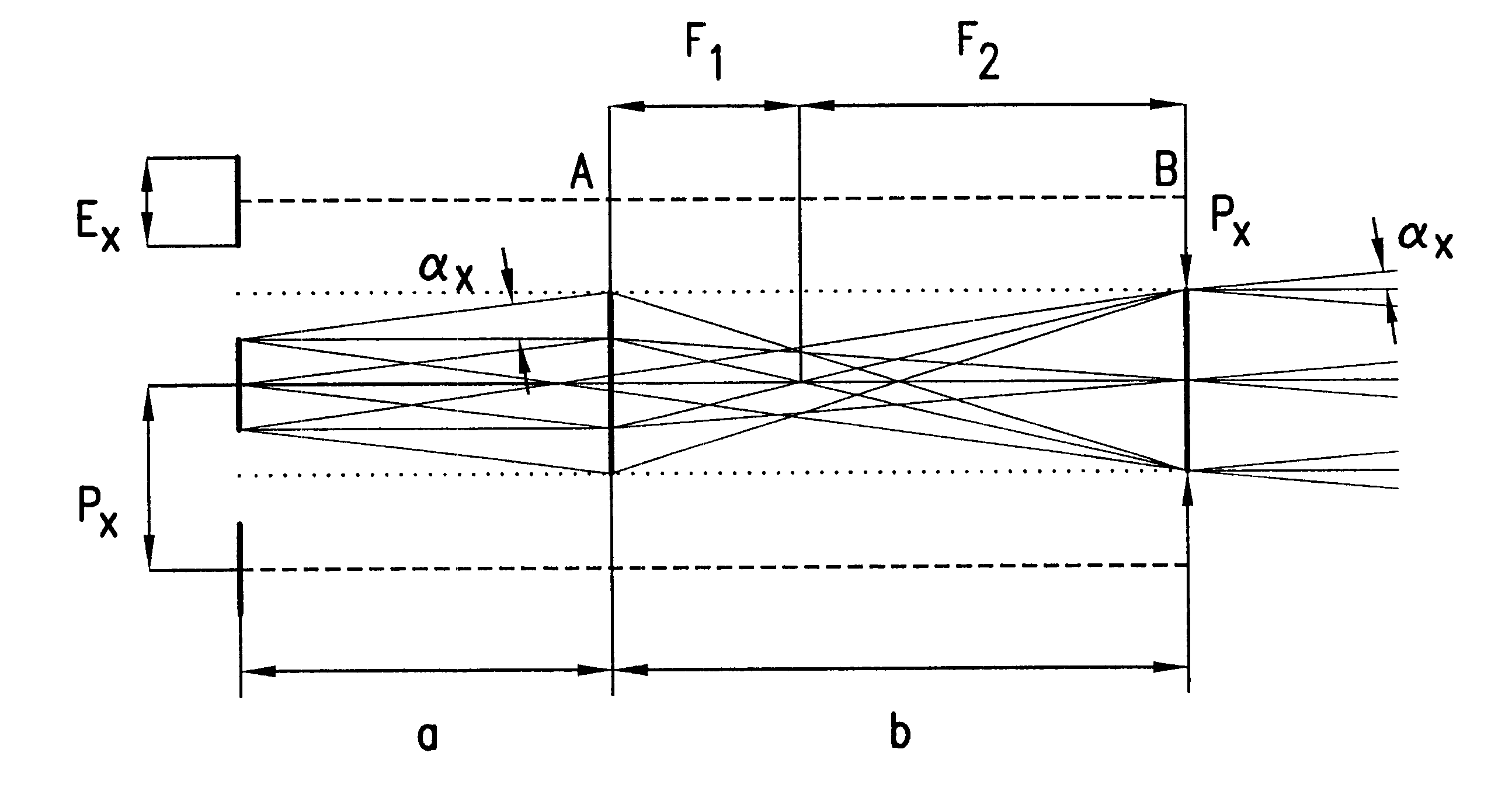
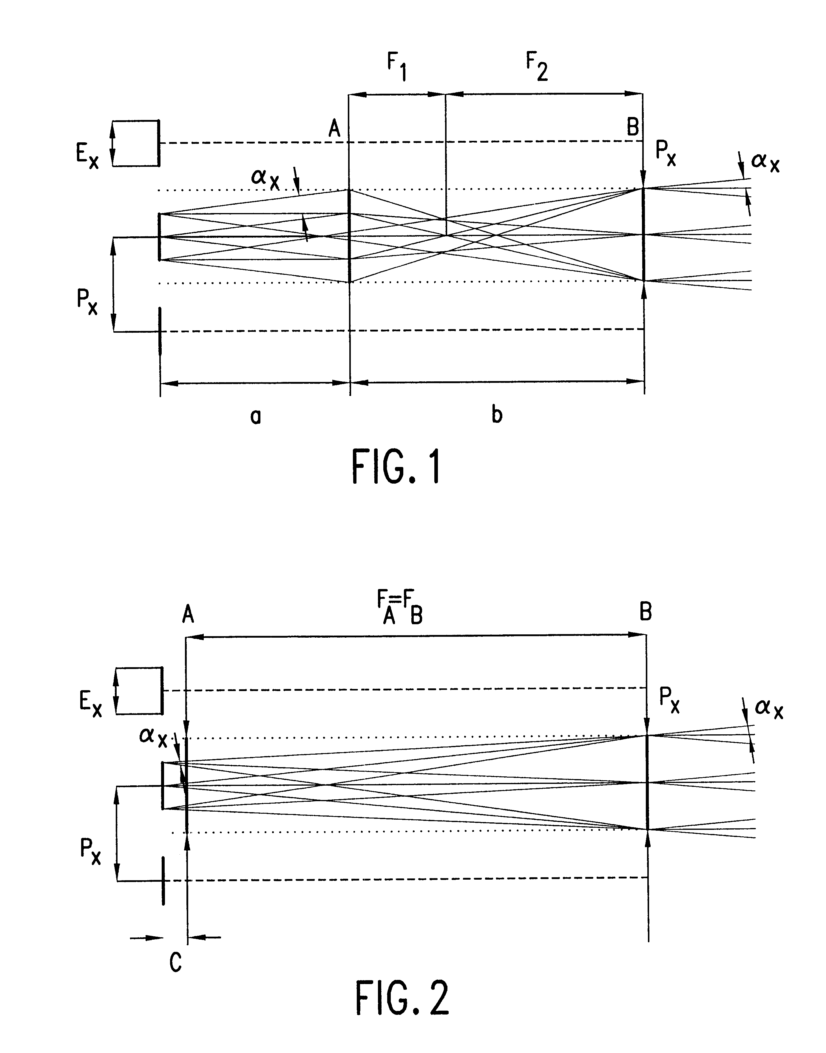
In FIG. 1, a view in the y-axis direction is presented of an emitter array with a number of extended emission surfaces in the form of lines extending in the x-direction having width (E.sub.x) and center-to-center distance (P.sub.x). This is the typical situation for diode laser bars where frequently E.sub.x / P.sub.x.gtoreq.0.5.

The divergence in the x-direction, that is, along the slow-axis, is designated by .alpha..sub.x. Due to this divergence, the ray bundles, if they were to spread unhindered, begin to overlap at the overlapping distance (a).

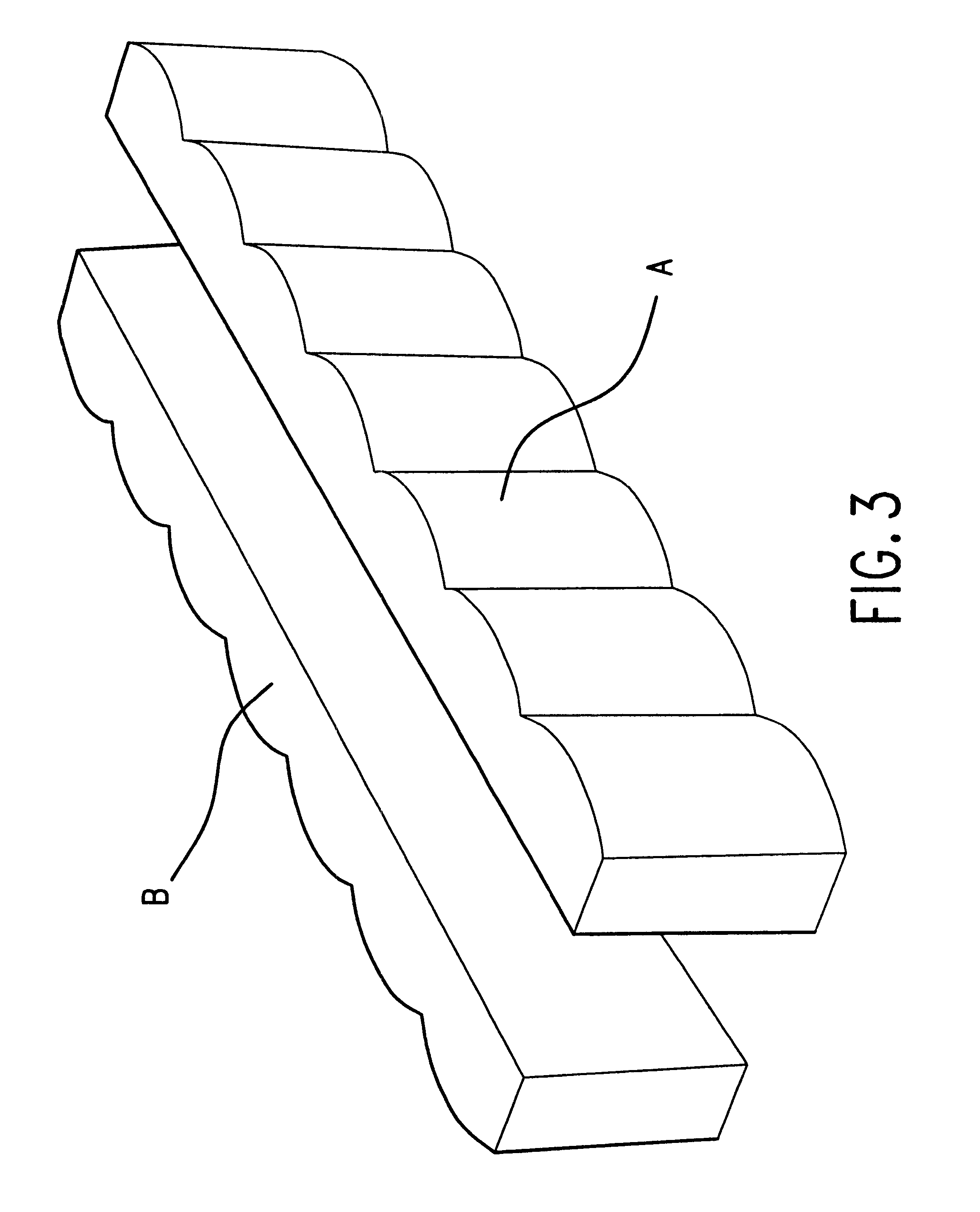
At the distance (a), a first cylindrical-lens array (A) is positioned whose parallel oriented cylindrical-lens surfaces lie in the y-direction and have width (P.sub.x). The focal length of the array (A) is (F.sub.1).

A second cylindrical-lens array (B) with focal length (F.sub.2) is positioned at a distance (b=F.sub.1 +F.sub.2) from the first cylindrical-lens arrays (A) wherein it constitutes an imaging plane for (A) with respect to the emitte...


PUM


Abstract

An optical emitter array with collimation optics in which a number of extended emitters are arranged side-by-side in the x-direction, having a specified divergence (alphax) in this direction and a center-to-center separation (Px) greater than the emitter size (Ex) and in which the collimation optics include a cylindrical lens array with a number of convergent cylindrical-lens surfaces each assigned to an emitter and having its cylindrical axis lying in the y-direction, arranged in front of the emitter array, characterized in that a first cylindrical-lens array with focal length (FA) is positioned in front of the emitters within an overlap distance (a) at which the ray bundles emerging from the emitters overlap at a separation (c) that is small in comparison to said focal length FA], a second cylindrical-lens array having the same focal length (FA) is positioned with a telescopic arrangement at a distance of this focal length (FA) away from the first cylindrical-lens array.

Description

The invention concerns an optical emitter array with collimation optics in which a number of extended emitters are arranged side-by-side in the x-direction, with a specified divergence .alpha..sub.x in this direction and a center-to-center separation (P.sub.x) greater than the emitter size E.sub.x and in which the collimation optics include a cylindrical lens array with a number of convergent cylindrical-lens surfaces each assigned to an emitter and having its cylindrical axis lying in the y-direction, arranged in front of the emitter array.PRIOR ARTSuch emitter arrays, with a number of optical sources that are linearly extended in the x-direction of width (E.sub.x) running along the x-axis in the shape of a linear matrix with center-to-center distance (P.sub.x) appear, for example, in high-power diode laser bars. The combined width of these laser bars lies in the range of a few millimeters. For concrete applications, it is generally necessary to subject these discontinuous beam pro...

Claims


Application Information

Patent Timeline
Patent Type & Authority Patents(United States)
IPC IPC(8): G02B27/09G02B3/00H01S5/40H01S5/00H01S3/00H01S5/20G02B3/06G02B27/00
CPCG02B3/005G02B3/0062G02B3/0068G02B27/09G02B27/0961G02B19/0014H01S5/4025G02B19/0057G02B27/0966H01S3/005H01S5/005H01S5/20
Inventor HAUSCHILD, DIRK
Owner LIMO GMBH
Why Eureka
Try Eureka