Systems and methods for controlling depths of a laser cut

a laser cutting and laser cutting technology, applied in laser beam welding apparatus, manufacturing tools, welding/soldering/cutting articles, etc., can solve the problems of affecting the performance of the adhesive, affecting the quality of the adhesive, and not meeting the dimensional tolerances or jamming of the die cutting tool

Inactive Publication Date: 2002-05-14
XEROX CORP
View PDF25 Cites 84 Cited by
  • Summary
  • Abstract
  • Description
  • Claims
  • Application Information

AI Technical Summary

Problems solved by technology

Microfluidic devices pose challenges in fluid path connection both within the microscopic componentry and also for the connection between a microfluidic device and macroscopic fluid containers or transporters.
Die cutting sheet stock containing one or more thick layers of adhesive can leave adhesive on the cutting tool and cause additional distortion, failure to meet dimensional tolerances or jamming of the die cutting tool.
Though the lubricant can be effective in this job, the lubricant can also modify or contaminate the adhesive so that it does not perform as well as an uncontaminated adhesive.
A large plastic fibers can create a leak path if it is located between the adhesive and sealing surface.
Smaller plastic fibers can be carried by ink into the die module and clog the fine jets in the die module or otherwise impede ink flow into or through the die module.
The adhesive strings can create difficulties in handling the fluid seal in the assembly equipment for the print cartridge or migrate to the surface of the die module containing the ink exit nozzles and interfere with the operation of the printing.
The shearing action of die cutting can cut through the adhesive layers but, since it does not remove material, the parted adhesive has a tendency to reflow and stick back together.
When this happens, the part may be difficult to remove on the manufacturing line or strings of adhesive can interfere with the assembly process.
The complications and shortcomings inherent in die cutting of fluid seals are significant design limitations on an ink jet print cartridge containing fluid seals.
The complications in the creation of parts with die cutting leads to significant problems with part yield and with loss of fully assembled print cartridges.
Design limitations, process limitations, and both part and print cartridge yield all lead to a significant cost associated with the die cutting process.
However, in each of these patents, none of the cuts form a sealed fluid path between two segments of the print cartridge, and the bulk part itself is cut using traditional cutting methods, while the laser is used only for forming features such as holes, lines, and the like.
It is more difficult, however, to form a cut to a controlled depth, or a "kiss" cut.
The difficulty arises from the fact that the laser beam is in contact with the material for the duration of the cutting process.
It may not be possible to control the process parameters and / or the thickness of the material to be cut to achieve a controlled depth cut to a satisfactory level of accuracy.
If control of the process parameters and / or material to be cut is possible, it may be very expensive, however, to control the process parameters and / or the thickness of the material to be cut to achieve a controlled depth cut to a satisfactory level of accuracy.
In some cases, closed-loop control alone is insufficient to insure the repeatability of the desired cut depth.

Method used


Image

  • Systems and methods for controlling depths of a laser cut
  • Systems and methods for controlling depths of a laser cut
  • Systems and methods for controlling depths of a laser cut

Examples


example

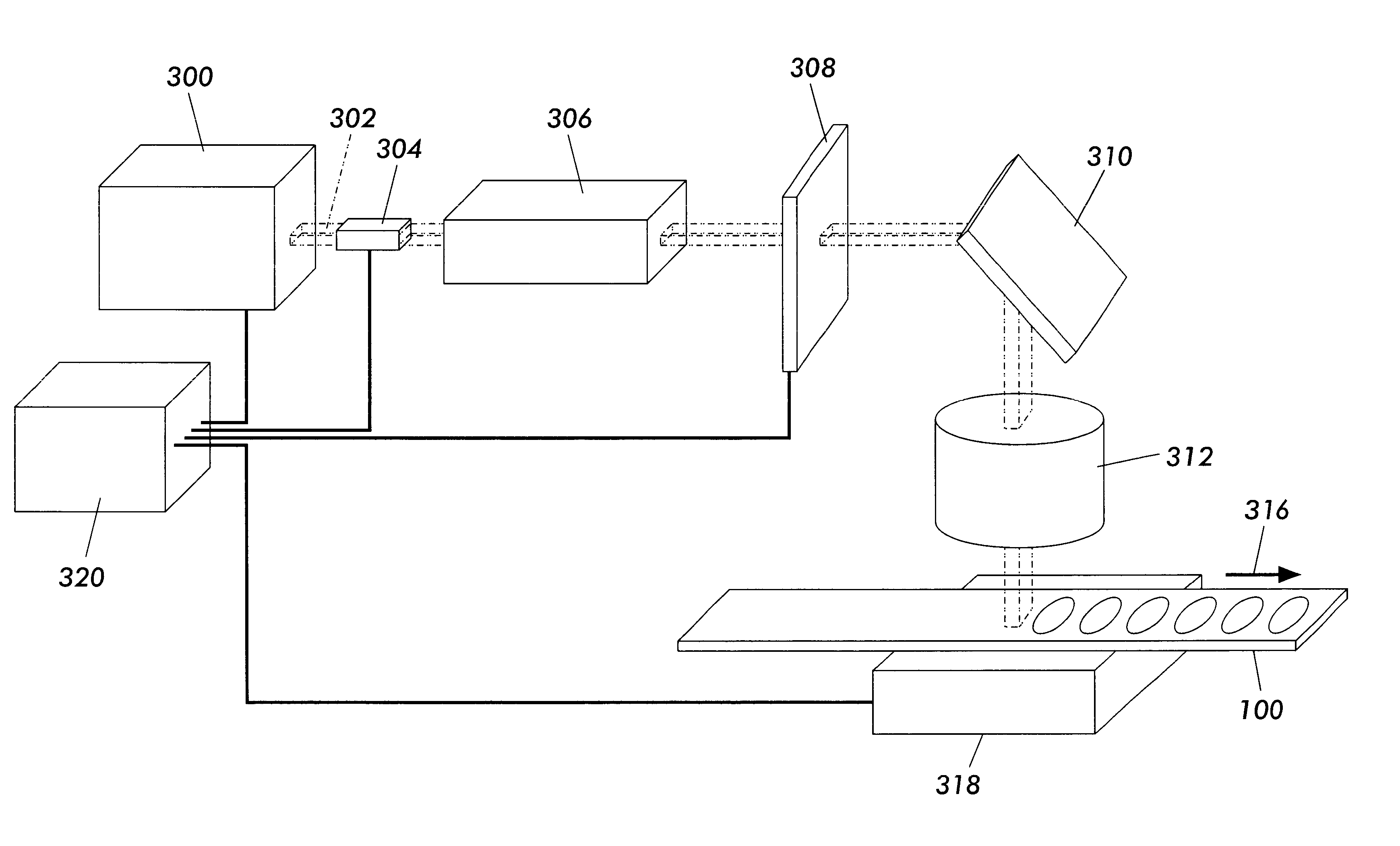
The sheet stock 100 of FIG. 5 includes the release liner 101, the substrate 103 and the carrier strip 105 formed of a polymeric material, such as MYLAR.RTM.. The sheet stock 100 also includes the adhesive layers 102 and 104 formed of, for example, phenolic nitrile. The sheet stock 100 may be considered a single thickness of MYLAR.RTM. for purposes of the example. The thickness of the sheet stock 100 is about 15.5 mils, or about 390 .mu.m. A 150 W CO.sub.2 laser operating at 9.4 .mu.m is used to cut the fluid seal around the remaining peripheral region while leaving the carrier strip 105 intact and also to cut out the sprocket holes 57 for the transport. The kiss cut 106 is formed entirely through the release liner 101, the adhesive layer 102, the substrate 103, and the adhesive layer 104. The total depth of the kiss cut 106 through the adhesive layer 104 is about 12.5 mils, or about 320 .mu.m. The kiss cut 106 extends about one third of the way into the carrier strip 105, which is a...


PUM

PropertyMeasurementUnit
laser wavelengthaaaaaaaaaa
distanceaaaaaaaaaa
thicknessaaaaaaaaaa

Abstract

A process for precision patterning or cutting of a sheet stock, such as an adhesive tape, includes the step of irradiating a surface of a sheet stock with an irradiation source to pattern or cut a part in the sheet stock and adjusting at least one of a beam width and the power of the irradiation source to form a cut in the sheet stock to a controlled depth. The method is particularly useful for precision cutting adhesive members, such as adhesive fluid seals, for an inkjet print cartridge.

Description

1. Field of InventionThis invention is generally related to controlling the depth of a laser cut by adjusting the beam size and / or the energy density or power of a laser.2. Description of Related ArtMaking a connection between two fluid containing or transporting components is widely practiced. In the new and emerging area of microfluidics, the fluid carrying components are small, in the range of 500 microns down to as small as 1 micron and possibly even smaller. For a general description of this class of devices, see for example, the conference proceedings "Microfluidic Devices and Systems," Proceedings of the SPIE, Vol. 3515 (1998).Microfluidic devices pose challenges in fluid path connection both within the microscopic componentry and also for the connection between a microfluidic device and macroscopic fluid containers or transporters. Such microfluidic devices are important in a wide range of applications that include drug delivery, analytical chemistry, microchemical reactors ...

Claims


Application Information

Patent Timeline
Patent Type & Authority Patents(United States)
IPC IPC(8): B23K26/40B23K26/00B23K26/08
CPCB23K26/0846B23K26/365B23K26/4085B23K26/407B23K26/4065B23K26/40B23K26/361B23K2103/16B23K2103/42B23K2103/50
Inventor ANDREWS, JOHN R.
Owner XEROX CORP
Why Eureka
Try Eureka