
Method and apparatus for transferring ions from an atmospheric pressure ion source into an ion trap mass spectrometer

a mass spectrometer and atmospheric pressure ion technology, applied in the direction of instruments, particle separator tube details, separation processes, etc., can solve the problems of high energy noise particles still entering the blocking potential, severe limit the signal-to-noise ratio in the mass spectral field, etc., to achieve the effect of reducing random nois

Inactive Publication Date: 2002-05-21
THERMO FINNIGAN
View PDF8 Cites 30 Cited by
  • Summary
  • Abstract
  • Description
  • Claims
  • Application Information

AI Technical Summary

Benefits of technology

It is an object of the present invention to provide an ion transfer assembly for directing ions from an atmospheric pressure ionization source of an ion trap mass spectrometer with reduced random noise and to a method of operation of the ion transfer assembly.
It is another object of the present invention to provide an ion transfer assembly employing multi-rod ion guides and means for applying appropriate RF and DC voltages to the rods which allows efficient transmission of ions to an ion trap while being able to reject random noise during mass analysis.
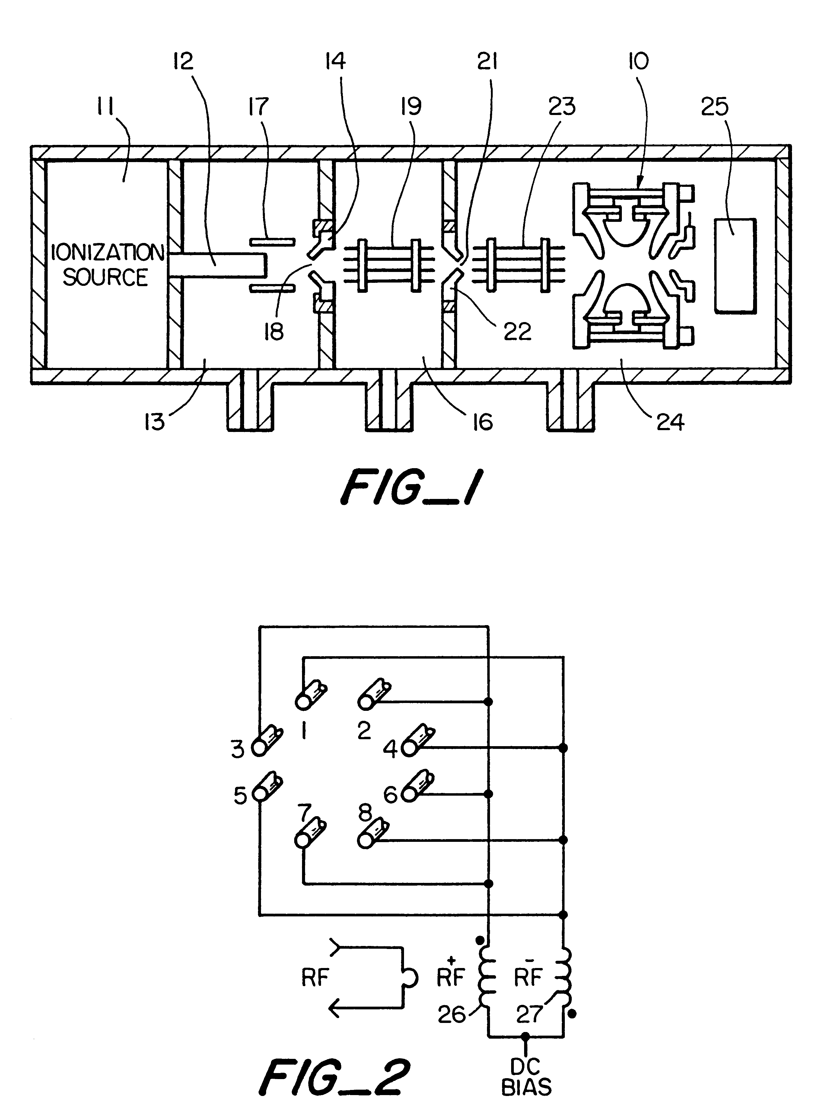
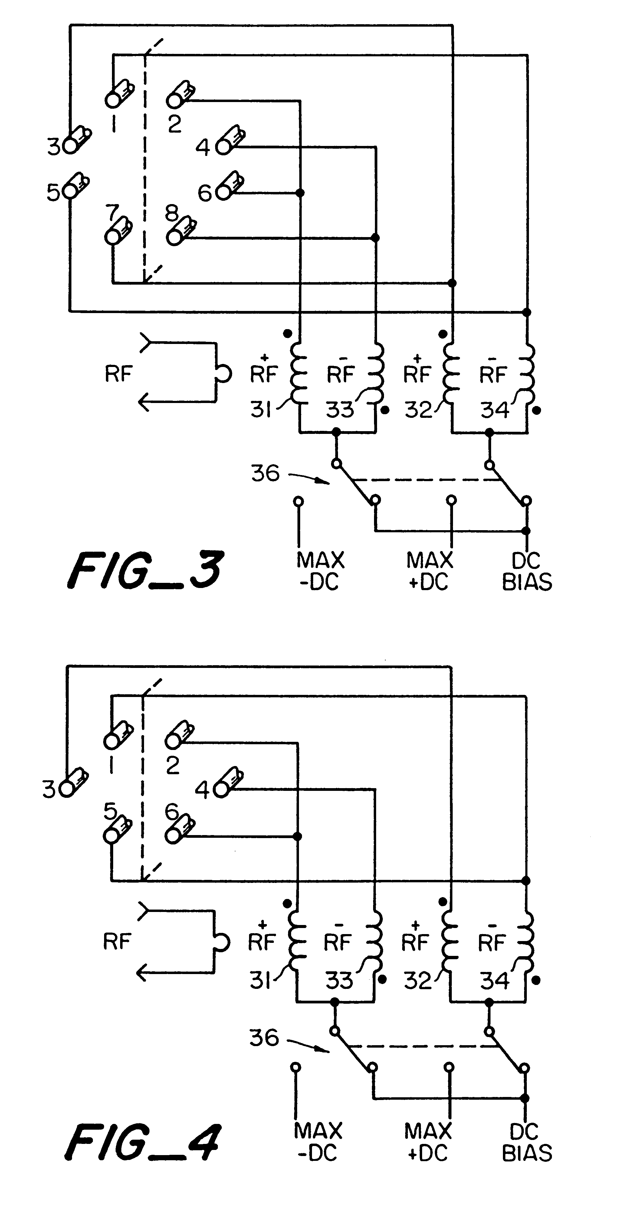
The foregoing and other objects of the invention are achieved by an ion transfer assembly which includes multi-rod ion guides for transferring ions from an atmospheric pressure ion source to an ion trap mass spectrometer, including means for applying RF and DC voltages to said rods to transfer ions into the ion trap for analysis by the mass spectrometer, and means for applying a DC voltage to said rods to create a dipolar field transverse to the ion path axis (with or without RF voltages), while the ions are analyzed by the mass spectrometer to minimize noise introduced by charged particles, desolvated charged droplets and ions from the atmospheric pressure ionization source by deflecting the particles and ions.

Problems solved by technology

Atmospheric pressure ion sources coupled to mass spectrometers by an ion transfer assembly often produce random noise spikes which can severely limit the signal-to-noise ratio in the mass spectra.
However, large voltages (>300V) are necessary for this method and high energy noise particles still may penetrate the blocking potential.

Method used


Image

  • Method and apparatus for transferring ions from an atmospheric pressure ion source into an ion trap mass spectrometer
  • Method and apparatus for transferring ions from an atmospheric pressure ion source into an ion trap mass spectrometer
  • Method and apparatus for transferring ions from an atmospheric pressure ion source into an ion trap mass spectrometer

Examples


Embodiment Construction

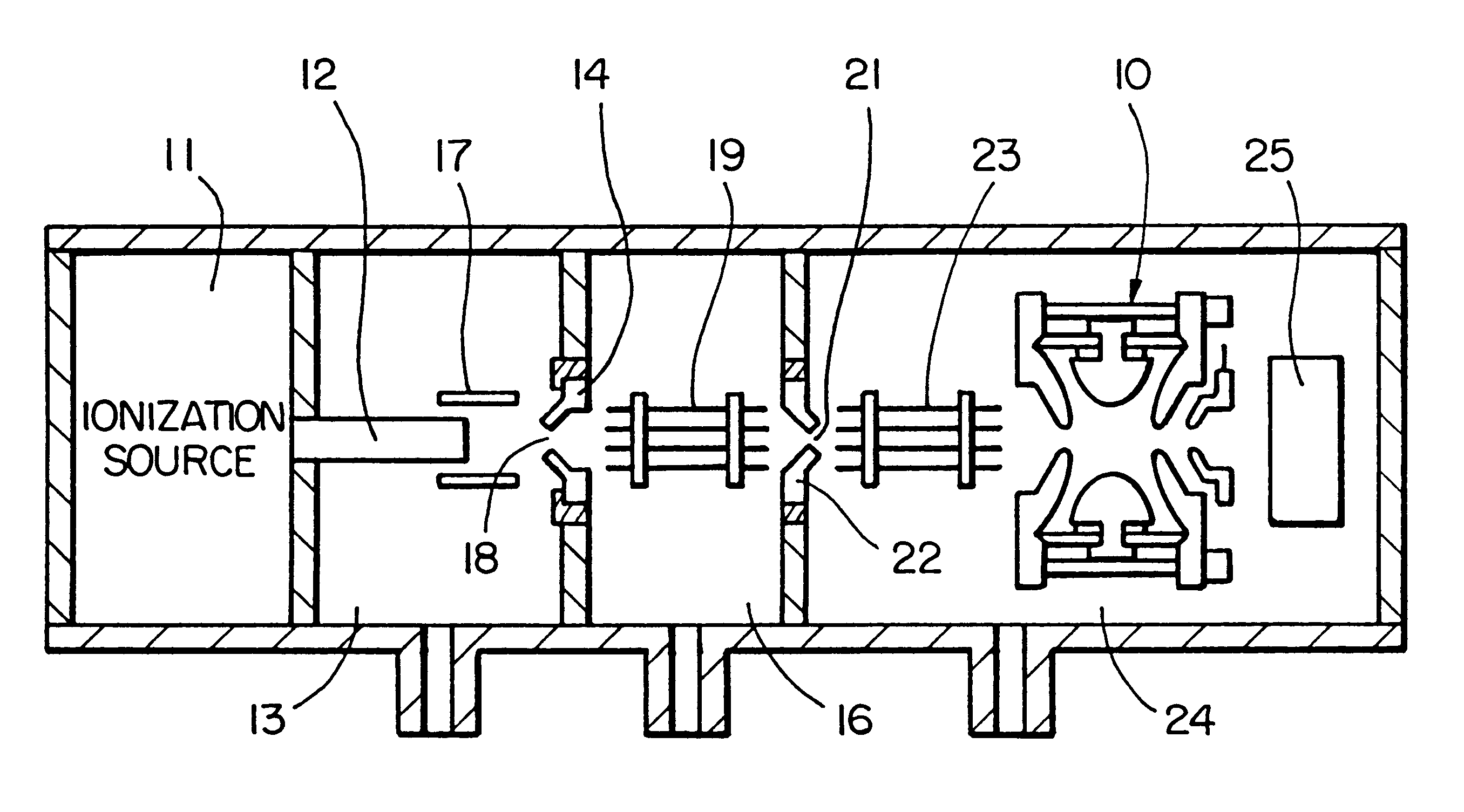
Referring to FIG. 1, an atmospheric pressure ionization source 11 such as an electrospray ionization source or an atmospheric pressure chemical ionization source is connected to receive a liquid sample from an associated apparatus such as a liquid chromatograph or syringe pump and which supplies a source of ions to an ion trap mass spectrometer 10. The source 11 forms ions representative of the effluent from the liquid chromatograph. The ions are transferred from the ion source to the mass spectrometer by an ion transfer assembly. Particularly, the ions are transported from the ion source through a capillary 12 into a first chamber 13 which is maintained at a lower pressure (.about.1 TORR) than the atmospheric pressure of the ionization source 11. Due to the differences in pressure, ions and gases are caused to flow through the capillary 12 into the chamber 13. The end of the capillary is opposite skimmer 14 which separates the lower pressure region 13 from a still lower pressure se...


PUM


Abstract

An ion transfer assembly for transferring ions from an atmospheric pressure ion source into an ion trap mass spectrometer with reduced random noise during analysis of the transferred ions. A method of reducing noise due to charged particles, undesolvated charged droplets, or ions in an ion trap mass spectrometer connected to an atmospheric pressure ionization source.

Description

An ion transfer assembly for directing ions from an atmospheric pressure ion source into an ion trap mass spectrometer with reduced random noise during the analysis of the transferred ions by the ion trap mass spectrometer.Atmospheric pressure ion sources coupled to mass spectrometers by an ion transfer assembly often produce random noise spikes which can severely limit the signal-to-noise ratio in the mass spectra. These noise spikes are believed to be caused by charged particles or clusters ions which reach the detector region at random times. The abundance of the noise can be affected by several parameters related to the ion source including spray stability, involatile buffer concentration, solvent flow, and sampling configuration. This noise has been shown in U.S. Pat. No. 5,171,990 to be reduced in an ion transfer assembly by moving the capillary off-axis from the skimming electrode at a small cost in sensitivity but with a large increase in signal-to-noise ratio.Ion trap mass ...

Claims


Application Information

Patent Timeline
IPC IPC(8): H01J49/04H01J49/42H01J49/02H01J49/34G01N27/62H01J49/06H01J49/22
CPCH01J49/063H01J49/061
Inventor SCHWARTZ, JAE C.SYKA, JOHN EDWARD PHILIP
Owner THERMO FINNIGAN
Learn More