Glass structures for nanodelivery and nanosensing

a nano-display and nano-sensing technology, applied in the direction of glass shaping apparatus, material strength using single impulsive force, ion implantation coating, etc., can solve the problems of difficult to coat successfully, damage to surfaces, and significant evanescent losses, and achieve good atomic force sensing capabilities and high transmission sub-wavelength optical apertures.

Inactive Publication Date: 2002-05-28
NANOPTICS
View PDF12 Cites 26 Cited by
  • Summary
  • Abstract
  • Description
  • Claims
  • Application Information

AI Technical Summary

Benefits of technology

This invention uses pulling technologies as applied to glass tubes to generate without any chemical etching a profile that is ideal to produce a high transmission subwavelength optical aperture with very good atomic force ...

Problems solved by technology

All of these structures, however, had less than optimized geometries at the tip and thus there were significant evanescent losses that resulted from the transmission of the electromagnetic radiation through the tip.
The coating, however, was problematic since the etching technology resulted in damaged surfaces that were difficult to impossible to coat successfully.
In addition, the angle required for coating such an etched structure was not compatible with the geometry of such untapered etched fibers.
F...

Method used


Image

  • Glass structures for nanodelivery and nanosensing
  • Glass structures for nanodelivery and nanosensing
  • Glass structures for nanodelivery and nanosensing

Examples


Embodiment Construction

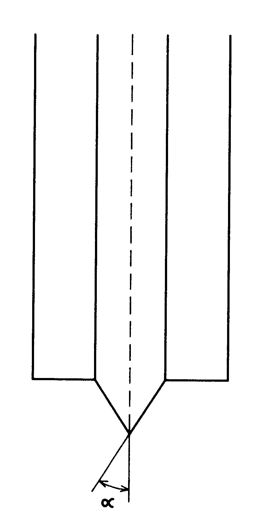
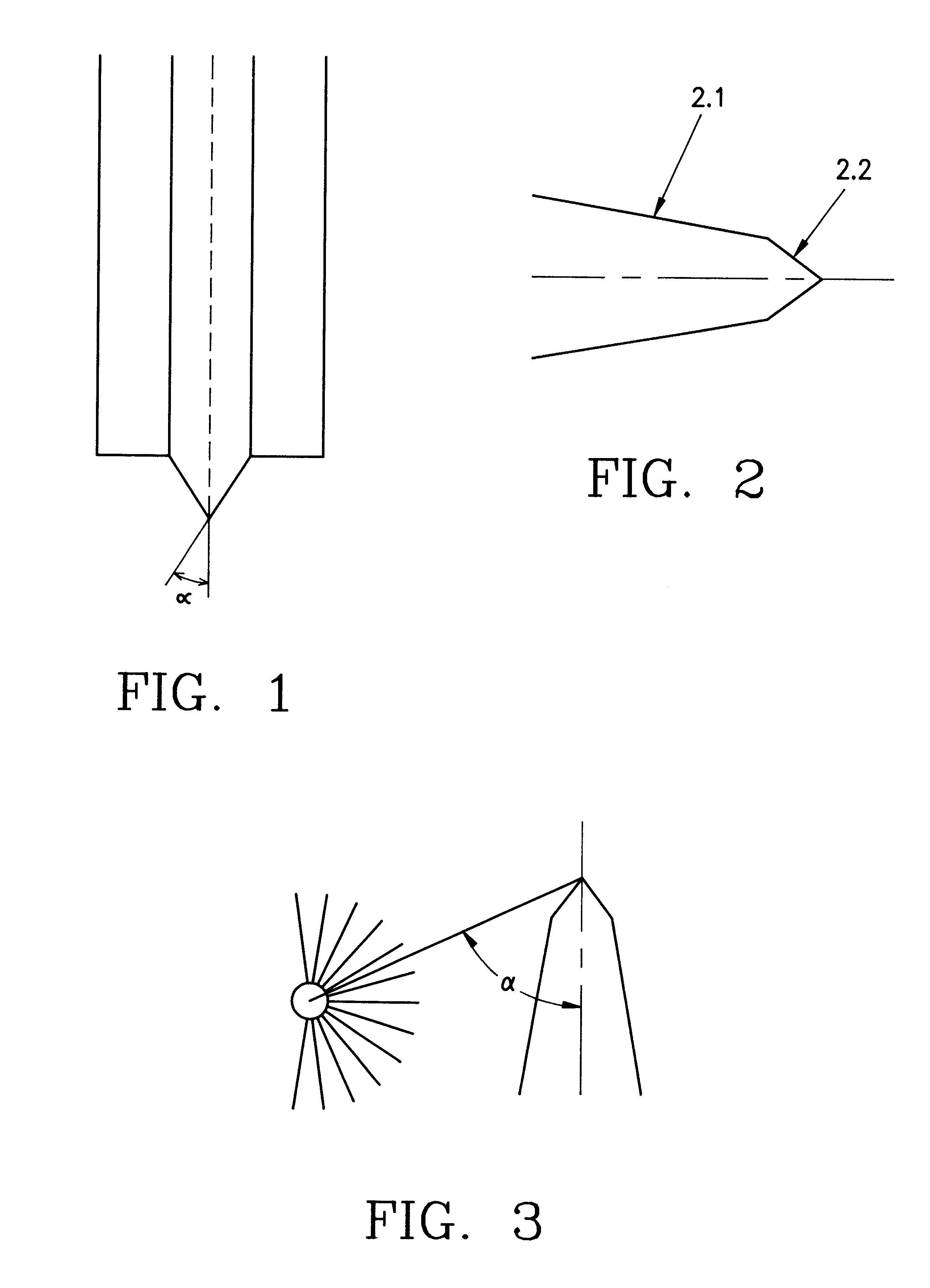
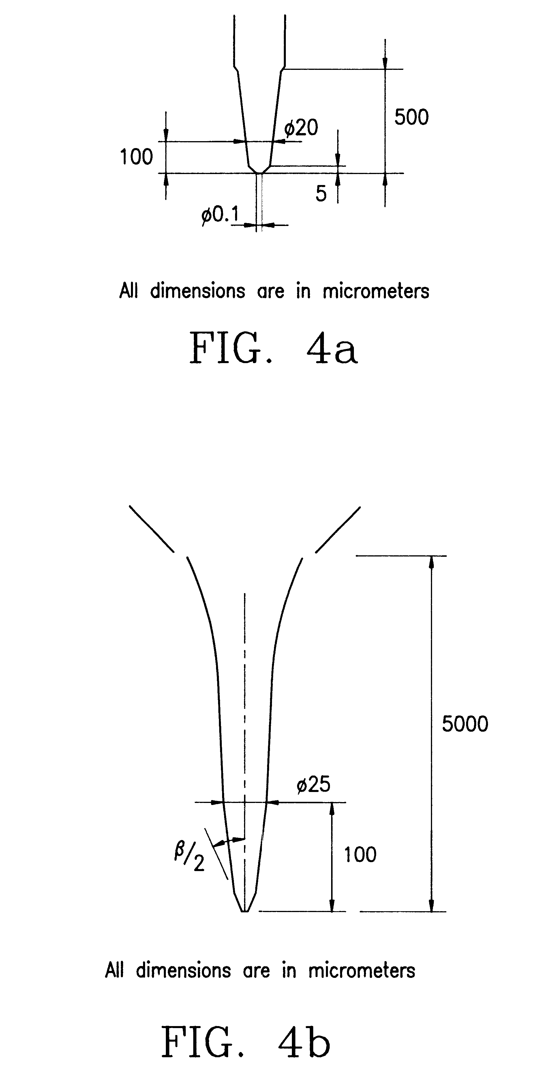
With pulling technology there are many parameters that can be adjusted to obtain the optimal profile. These are: 1. heat or temperature, 2. the geometric region that is heated, called the filament, 3. the velocity of the pulling that is measured as the glass softens and begins to separate under a constant load and this velocity is determined by the time of heating, 4. the delay between the start of the pulling and turning off the heating element and 5. the tension of the pulling. These can all be microprocessor controlled to develop a geometry in which the glass is first tapered to a dimensionality that is above the cut-off for the propagation of electromagnetic radiation in a metallic waveguide (FIG. 2.1 ) and is then cooled before a second tapering cycle is entered in which a cone angle between 30-40.degree. (FIG. 2.2 ) is achieved by multiple pulling cycles. This geometry is shown in FIG. 2. The number of these later cycles depends on the final outer diameter of the tip. In addit...


PUM

PropertyMeasurementUnit
Angleaaaaaaaaaa
Angleaaaaaaaaaa
Frequencyaaaaaaaaaa

Abstract

A device comprising a tapered glass structure produced from glass capillary tube by pulling technologies to generate an optimized geometry for high transmission efficiency of electromagnetic radiation. The device being bent near the tip to produce a cantilevered structure suitable for normal force sensing in a variety of attractive, repulsive and non-contact imaging modes.

Description

1. FIELD OF THE INVENTIONThis invention allows the production of tapered straight and cantilevered structures that are optimized for the maximal nanodelivery of electromagnetic radiation and chemicals and for the maximal sensitivity in the nanosensing of ionic phenomena with high efficiency. These structures are generated so that they can simultaneously act as force sensors with excellent dynamic characteristics. Unlike previous attempts at obtaining such elements with chemical etching techniques our methodology is based solely on the application of glass pulling technologies with specific protocols that can minimize the subwavelength travel of light waves and can maximize the dynamic capabilities of these devices. Unlike the glass etching techniques these glass pulling technologies are universally, applicable to glass micropipettes and fibers. In addition optimal geometries of force sensing glass micropipettes are invented for the optimal delivery of chemicals in nanoguantities in ...

Claims


Application Information

Patent Timeline
IPC IPC(8): B01L3/02C03B23/09C03B37/10C03B23/00C03B23/08C03B37/075C03B37/15C23C14/50G01N3/30G01N3/317G02B6/255G02B6/26C23C14/22G01N3/00G01N3/06G02B6/24
CPCB01L3/0244G02B6/262C03B23/08C03B23/091C03B23/096C03B37/0756C03B37/15C23C14/225C23C14/505G01N3/317G02B6/2552B01L3/0255B01L2200/12G01N2203/0647G01N2203/0676G02B6/241
Inventor LEWIS, AARONFISH, GALINAKOKOTOV, SOPHIAKHACHAIRYAN, EDWARDIGNATOV, ANDREYGLAZER, RIMMAKOMISSAR, ANATOLYHEIFEZ, YURISTRINKOVSKY, ALINALIEBERMAN, KLONY
Owner NANOPTICS
Why Eureka
Try Eureka