Fixed-point crucible, fixed-point temperature realizing apparatus using the crucible and temperature calibration method

a technology of fixed-point crucibles and temperature realizing apparatuses, which is applied in the direction of heat measurement, instruments, calibrators, etc., can solve the problems of difficult to use strip lamps with high accuracy, large deterioration of accuracy of temperature scales, and enormous efforts to realize temperature scales. high accuracy

Inactive Publication Date: 2002-06-04
NAT INST OF ADVANCED IND SCI & TECH
View PDF15 Cites 20 Cited by
  • Summary
  • Abstract
  • Description
  • Claims
  • Application Information

AI Technical Summary

Benefits of technology

According to the fixed-point temperature realizing apparatus and the temperature calibrating method using the apparatus of the present invention, since fixed-point temperatures in the high temperature region can be realized and thermometers such as the radiation thermometer, the thermocouple, the resistance thermometer and the like can be calibrated by interpolation, accuracy can be greatly improved.
Further, since calibration can be carried out by interpolation, the accurate evaluation of the characteristics of a highly-accurate standard radiation thermometer, which is conventionally required, is unnecessary, whereby a calibration job is remarkably simplified and a system for providing a temperature scale can be upgraded.
Furthermore, the palladium wire method is unnecessary in the calibration of the thermocouple. In addition, in the development of a high temperature thermocouple which is carried out hereinafter, the characteristics of the thermocouple such as the stability, the variation among different thermocouples, and the like can be evaluated with high accuracy, which can also contribute to the improvement of the characteristics of the thermocouple.

Problems solved by technology

Since the temperature scale maintained by the strip lamp or the radiation thermometer, which are employed because a fixed-point crucible above the copper point is not available, depends on the extrapolation, the accuracy of the temperature scale is greatly deteriorated.
Further, it requires enormous efforts to realize temperature scale in high accuracy such as the use of a radiation thermometer of high accuracy, the accurate evaluation of the characteristics of the radiation thermometer.
However, since it still depends on the extrapolation, resulting uncertainty in temperature scale realization and maintenance is about 1.2.degree. C. at 2000.degree. C.
Thus, not only it is difficult to use the strip lamp with high accuracy but also the strip lamp must be used with an inert gas enclosed therein because the tungsten of the ribbon is evaporated at a temperature above 2000.degree. C.
As a result, stable characteristics of the strip lamp cannot be obtained due to the convection of the inert gas.
However, it lacks practicality because a problem arises in that when the alumina crucible is repeatedly used, the crucible is broken.
This is because the alumina is susceptible to thermal shock and made brittle thereby.
Sufficient accuracy cannot be obtained in the calibration of the thermocouple carried out by the palladium wire method.
This is because reproducibility obtained thereby is only about 1.degree. C. and that accuracy in interpolation is deteriorated because even the copper point as the nearest fixed-point is about 500.degree. C. apa
This is because that the processability of tungsten is bad, it is difficult to enclose molten alumina into a lateral crucible and sufficient accuracy cannot be obtained since a blackbody cavity whose emissivity is near to 1 cannot be formed due to the low emissivity of the tungsten.
Thus, when the same method is used in a temperature region higher than the copper point, a fixed-point temperature cannot be realized because a freezing point cannot help being lowered by the dissolving of graphite.
Furthermore, the palladium wire method is unnecessary in the calibration of the thermocouple.

Method used


Image

  • Fixed-point crucible, fixed-point temperature realizing apparatus using the crucible and temperature calibration method
  • Fixed-point crucible, fixed-point temperature realizing apparatus using the crucible and temperature calibration method
  • Fixed-point crucible, fixed-point temperature realizing apparatus using the crucible and temperature calibration method

Examples


Embodiment Construction

Embodiments of a fixed-point crucible, a fixed-point temperature measuring apparatus using the crucible and a temperature calibrating method using the apparatus according to the present invention will be described below with reference to the drawings.

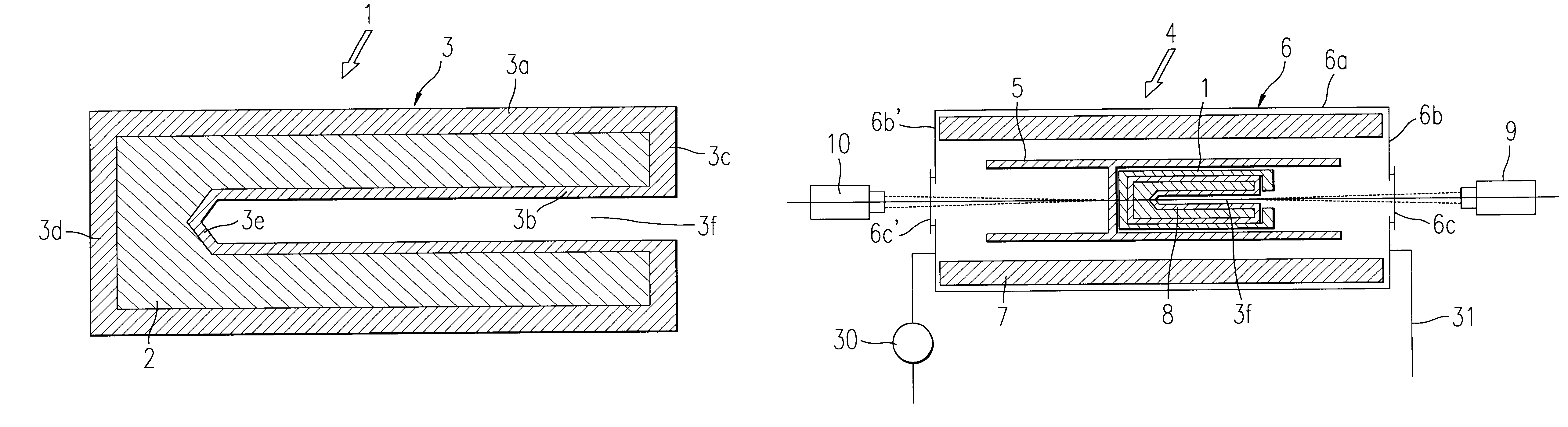
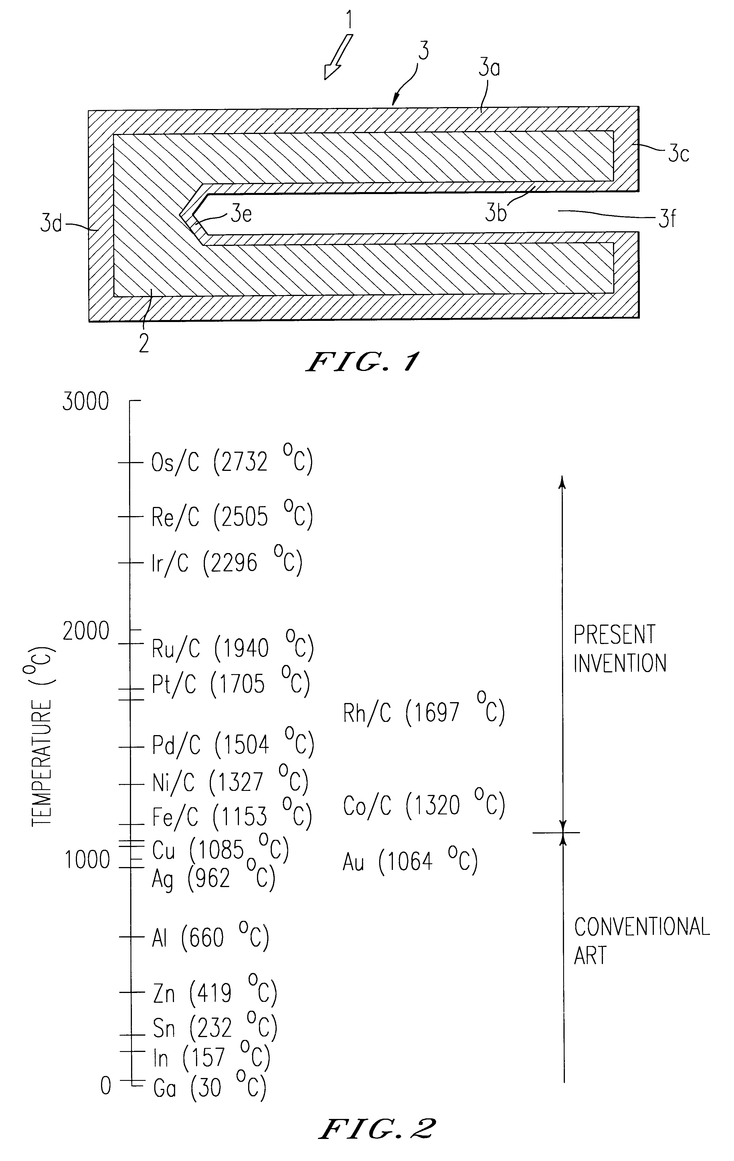
FIG. 1 is a sectional view showing an embodiment of the fixed-point crucible according to the present invention.

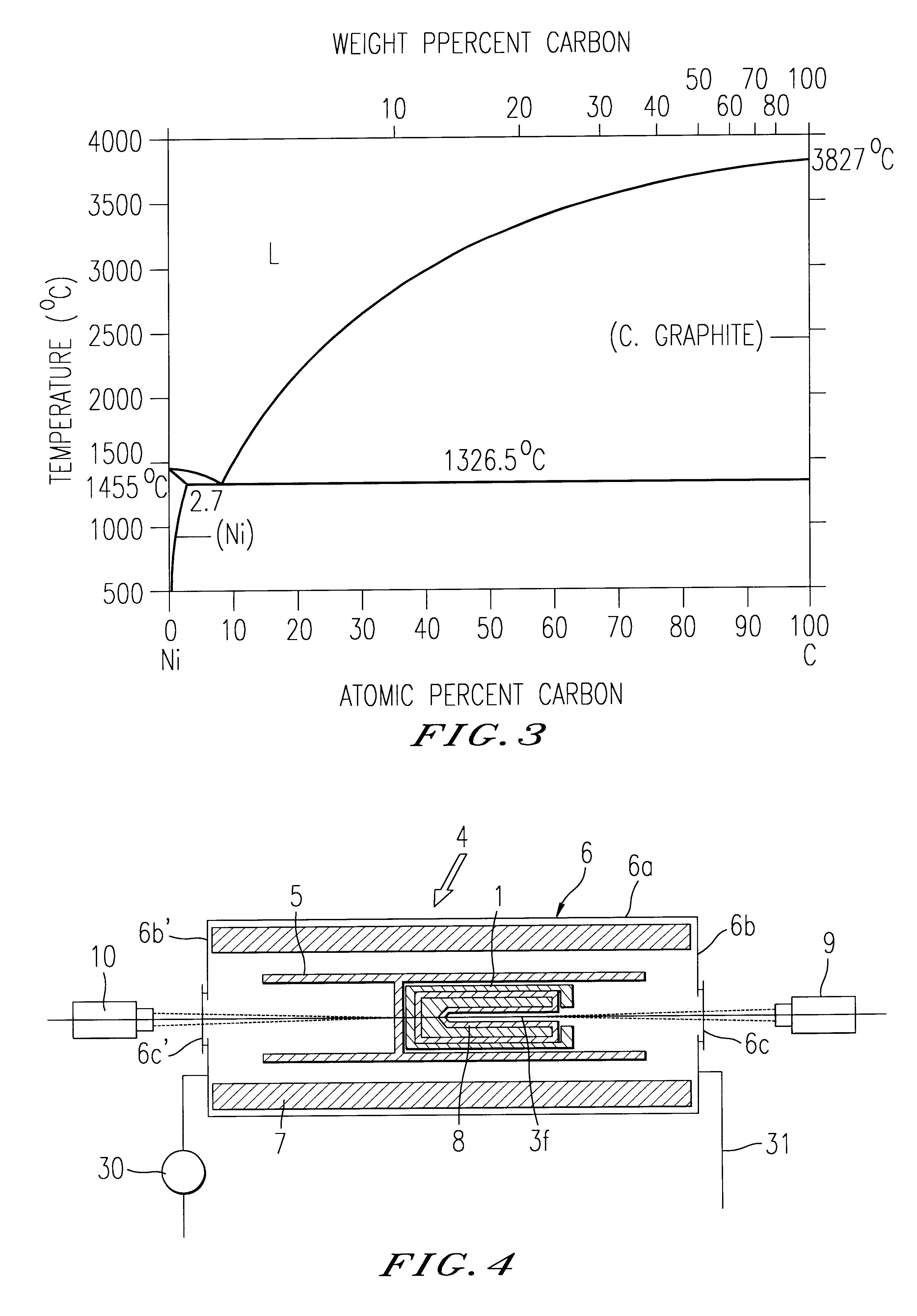
In FIG. 1, the fixed-point crucible 1 is composed of a graphite crucible 3 and an eutectic structure of carbon and metal 2 enclosed in the wall of the crucible 3 and uses the temperature of the melting point and the freezing point of the eutectic structure of carbon and metal 2 as a fixed-point temperature.

To describe the fixed-point crucible in more detail, the wall of the graphite crucible 3 has a hollow double-walled cylindrical shape concentrically including an outer cylinder 3a and an inner cylinder 3b. The outer cylinder 3a and the inner cylinder 3b are coupled with each other at ends thereof through an end wall 3c, and ...


PUM

PropertyMeasurementUnit
temperatureaaaaaaaaaa
fixed-point temperaturesaaaaaaaaaa
melting pointaaaaaaaaaa

Abstract

The present invention is to realize fixed points in a temperature region exceeding the melting point of copper, thereby highly accurately calibrating all the thermometers used in a high temperature region such as a radiation thermometer, a thermocouple, and the like. A fixed-point crucible 1 comprises a crucible composed of carbon and a fixed-point material of high melting point enclosed in the wall of the crucible. The fixed-point material is carbon-metal eutectic structure. The crucible 1 is disposed in a temperature-variable furnace 6, the environmental temperature of the crucible 1 is increased and decreased by the temperature-variable furnace 6, the temperature of the cavity in the crucible 1 at the time is measured with a thermometer 9 and the thermometer 9 is calibrated from the state of the temperature variation measured.

Description

The present invention relates to a fixed-point crucible necessary to calibrate a thermometer, for example, a radiation thermometer, a thermocouple and the like used in a high temperature region exceeding 1000.degree. C., a fixed-point temperature realizing apparatus and a thermometer calibrating method using the apparatus.RELATED ARTWhen thermometers are calibrated, a freezing point or a melting point of metal is employed as a defining fixed-point in the temperature region above room temperature. A fixed-point crucible is used as a method of realizing the fixed-point temperature.Graphite crucibles, in which pure metal is cast as a fixed-point material of high melting point, have been usually used as the fixed-point crucible. A thermometer is calibrated making use of such a phenomenon that when the liquid phase and the solid phase of the fixed-point material coexist in the crucible, the temperature of the crucible is not varied due to latent heat of melting. This phenomenon is realiz...

Claims


Application Information

Patent Timeline
Patent Type & Authority Patents(United States)
IPC IPC(8): G01K15/00
CPCG01K15/002
Inventor YAMADA, YOSHIRO
Owner NAT INST OF ADVANCED IND SCI & TECH
Why Eureka
Try Eureka