Balloon trajectory control system

a control system and balloon technology, applied in the direction of lighter-than-air aircraft, transportation and packaging, weapons, etc., can solve the problems of large power requirements for propellers, restricted attainable altitude and payload masses of airships, and inability to achieve significant power for balloon systems

Inactive Publication Date: 2002-06-11
GLOBAL AEROSPACE
View PDF9 Cites 48 Cited by
  • Summary
  • Abstract
  • Description
  • Claims
  • Application Information

AI Technical Summary

Benefits of technology

It is a further object of the current invention to provide a balloon control device that passively exploits natural wind conditions, permits the balloon to remain at a fixed altitude and induces air flow past the balloon to sweep away contaminants.
It is a further object of the current invention to provide a device which requires very little power and can be operated efficiently at night.
The inventive device disclosed uses very little power to operate, can operate at night, can be made of very lightweight materials, does not require detailed knowledge of the wind field, allows the balloon to remain at a fixed altitude, generates control forces having a greater range of magnitude and direction as compared with a comparably sized drag device, can change the direction of the control force fairly rapidly, and operates at an altitude lower than the balloon where the air density is greater so that the device can be relatively small compared with the balloon.

Problems solved by technology

However, the attainable altitudes and payload masses for airships are quite restricted in comparison to those of free balloons.
Propellers require substantial power to drag a balloon through the atmosphere.
Also, significant amounts of power are typically unavailable for balloon systems due to the inherent need to keep weight to a minimum.
If the power is generated using solar cells, then nighttime operation is not possible without very heavy batteries.
If combustion provides the propulsive power, then the duration is limited by the weight of portable fuel.
These requirements for propulsive power are at odds with the need to keep the weight low.
According to these references, the operation of such devices would be limited to a couple of days due to the large propulsive energy required.
In addition, both combustion engines and electric engines suffer from the difficulty of rejecting the substantial waste heat to prevent overheating in the low density atmosphere.
Since winds can have speeds in the range 15-50 m / s (50-150 ft / s), this leads to significant power requirements.
This use of consumables ultimately limits the duration of the mission.
Furthermore, carrying the ballast reduces the weight available for the payload.
Another drawback is that many balloon-borne science instruments, especially those used in astronomy and astrophysics experiments, need to be above most of the atmosphere (99%) and cannot acquire high quality data at lower altitudes.
Such detailed knowledge is usually unavailable during the flight.
Thus, sport balloon flying often involves significant trial-and-error in seeking favorable altitudes.
This altitude control scheme does not work in the stratosphere; it requires the particular variation of temperature and pressure in the troposphere.
However, the direction of the force is restricted essentially to the direction the wind is blowing at the altitude of the parachute.
It is possible to use a winch to raise or lower the parachute to altitudes with different wind directions, but this may require a significant amount of time for changing the direction of the force.
Also, a significant amount of power may be required to raise such a device in the presence of both gravity and aerodynamic drag.
Contaminants from the balloon itself, such as the helium lifting gas, or volatiles from the envelope material, can interfere with these sensitive measurements.

Method used


Image

  • Balloon trajectory control system
  • Balloon trajectory control system
  • Balloon trajectory control system

Examples


second embodiment

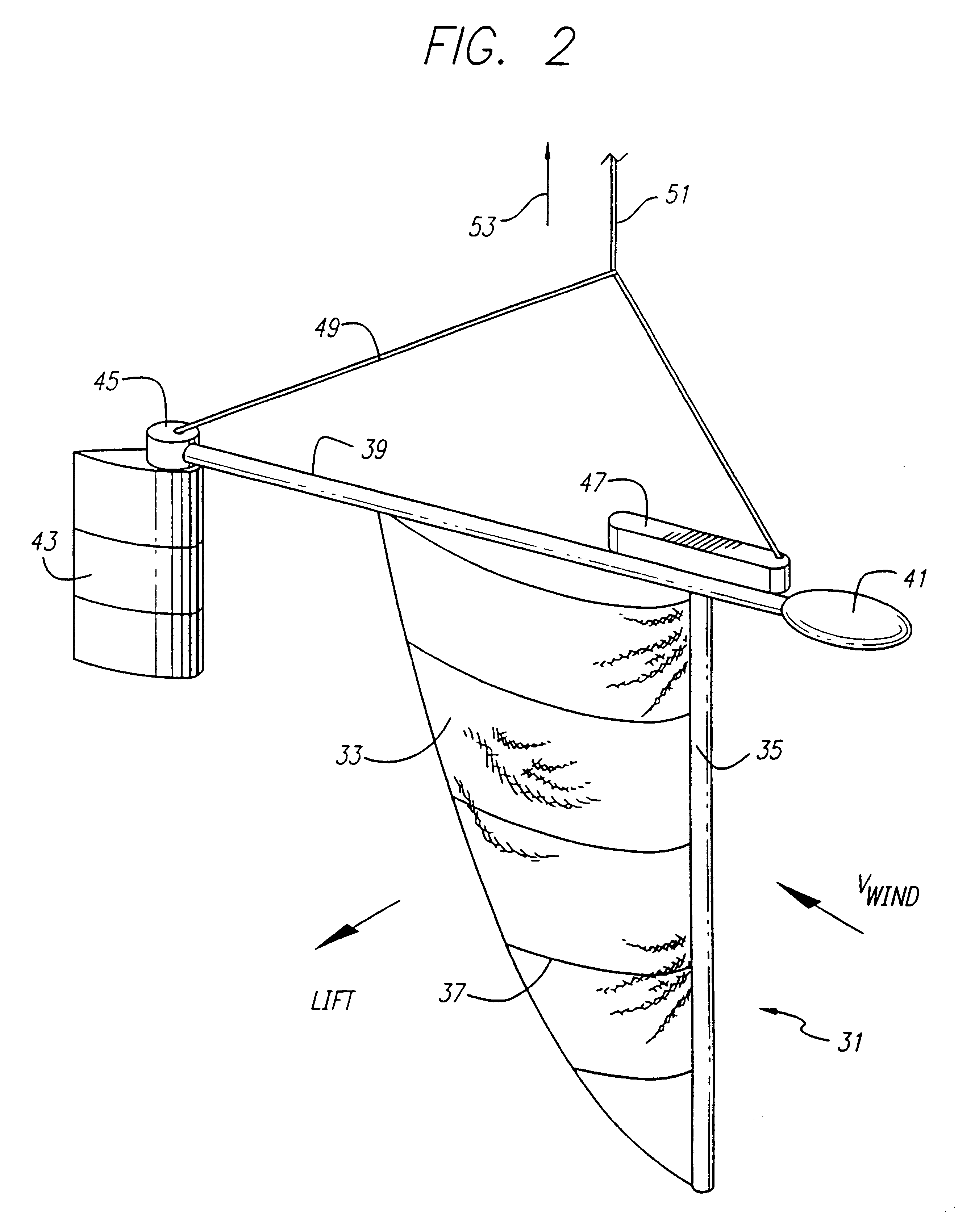
a balloon trajectory control device is shown in FIG. 2. The main lift-generating element 31 is shown comprising an inverted sail 33, a mast 35, and a plurality of battens 37. The sail 33 and mast 35 are attached to a boom 39 having a front end and a back end. A counterweight 41 is attached to the front end of the boom. A rudder 43 and rudder actuator 45 are attached to back end of the boom. A control module 41 is mounted at a convenient location. The control module 41 includes a power source (not shown), if required, comprising a battery and a solar panel. A yoke 49 connects the boom to a tether 51. The upper end of the tether is attached to a winch 53 (not shown) mounted to an LTA system (e.g. a gondola of a balloon).

The operation of the sail version of the trajectory control device is very similar to the operation of the wing version (FIG. 1). The use of a sail rather than a double-sided airfoil section is expected to have somewhat less efficient aerodynamic performance. However, ...

third embodiment

a trajectory control device is shown in FIG. 3. In this embodiment, the stabilizing surface is placed ahead of the main lifting surface. When used on an aircraft, the small forward stabilizer is called a canard and the arrangement is referred to as a canard configuration.

The operation of the canard configuration is very similar to the operation of the preferred embodiment with its conventional arrangement (stabilizer behind the main wing). Although the canard configuration looks unstable, the requirement that the center of gravity be ahead of the neutral point is identical to that of the conventional configuration.

fourth embodiment

a trajectory control device is shown in FIG. 4. In this embodiment, a biplane arrangement is used for the main lifting generating element. It is shown with a conventional arrangement with the stabilizer behind the main wings.

The operation of the device with a biplane (or triplane, or more) is identical to the operation with a single wing. An advantage of this configuration is structural: the box-like structure has inherently greater stiffness than for a monoplane. Similarly, the rudder could comprise multiple surfaces as well.


PUM


Abstract

A device to provide control of the trajectory of a lighter than air vehicle, such as a balloon, is provided. A lifting device, such as a wing on end, is suspended on a tether well below the balloon to take advantage of the natural variation in winds at different altitudes. The wing can generate a horizontal lift force that can be directed over a wide range of angles. This force is transmitted to the balloon by the tether. Due to this force, the balloon's path is altered depending on the relative sizes of the balloon and the wing. A relatively small amount of power is needed to control the system, possibly with a rudder. As the energy of the wind provides most of the force, the wind's energy does most of the work. The balloon is able to avoid hazards, to reach desired targets, to select convenient landing zones, and to provide other operational advantages. As a result, fewer flights must be terminated early due to an inability to control the trajectory, and it is easier to obtain permission to launch since a planned flight path can be achieved within a greater range of conditions.

Description

1. Field of InventionThe present invention relates generally to controlling the trajectory of a balloon and more specifically to a control device located remotely from a balloon for providing desired forces for trajectory control.2. Description of Related ArtVery few devices have been used to control the trajectories of free balloons, such as balloons carrying scientific atmospheric sensing instruments. Propeller-driven airships can control their trajectories, for example, through modulation of the speed and the pitch of a propeller. However, the attainable altitudes and payload masses for airships are quite restricted in comparison to those of free balloons. Free balloons carrying science instruments typically drift freely in the prevailing wind at a desired operating altitude. In many cases, launch of such balloons must be delayed until forecast winds are projected to carry the balloon system into a region of interest or away from a forbidden zone. Frequently, such balloon flights...

Claims


Application Information

Patent Timeline
Patent Type & Authority Patents(United States)
IPC IPC(8): B64B1/00B64B1/44B64B1/40
CPCB64B1/00
Inventor AARON, KIM MAYNARD
Owner GLOBAL AEROSPACE
Why Eureka
Try Eureka