Process for conveyance of powder materials in hyperdense phase applicable to bypassing obstacles

a technology of hyperdense phase and conveyance process, which is applied in the direction of conveyors, bulk conveyors, transportation and packaging, etc., can solve the problems of low permeability of the medium to gas injected at pressure p.sub.f, limited gas flow to a very small quantity, and low system maintenan

Inactive Publication Date: 2002-06-11
ALUMINUM PECHINEY
View PDF3 Cites 24 Cited by
  • Summary
  • Abstract
  • Description
  • Claims
  • Application Information

AI Technical Summary

Problems solved by technology

One particular problem is related to the continuous feed of the powder material regulated as a function of consumption requirements of the said material.
Furthermore, since the interstitial distance between particles does not increase, the permeability of the medium to gas injected at pressure p.sub.f is very low and limits the gas flow to a very small quantity.
low system maintenance, low wear due to the low product circulation velocity,
The applicant observed f...

Method used


Image

  • Process for conveyance of powder materials in hyperdense phase applicable to bypassing obstacles
  • Process for conveyance of powder materials in hyperdense phase applicable to bypassing obstacles
  • Process for conveyance of powder materials in hyperdense phase applicable to bypassing obstacles

Examples


example 2

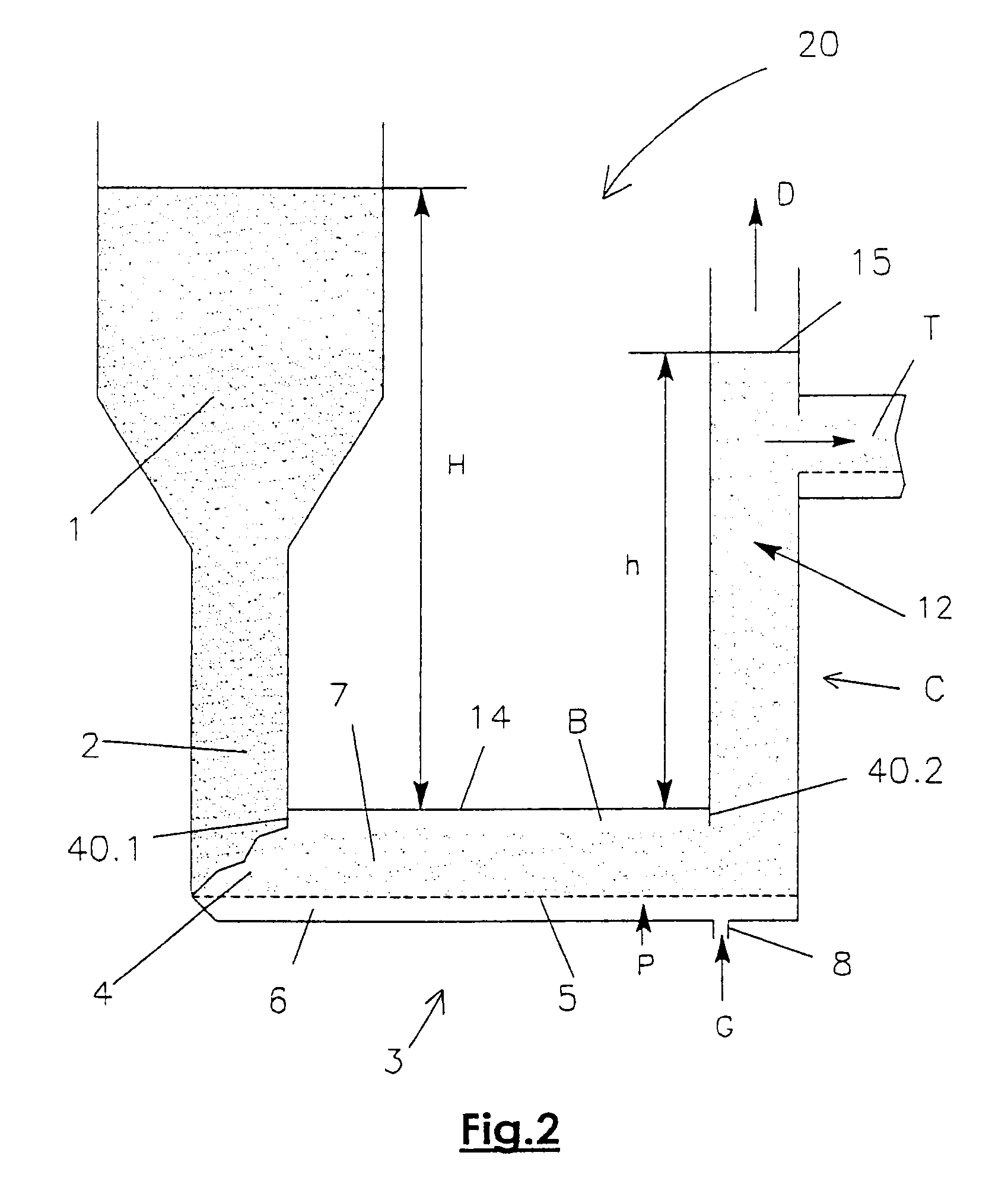
Extraction at the Silo Bottom (FIG. 2)

Another application of the siphon in the hyperdense phase is extraction of a powder product from the bottom of a silo.

The silo is not always located very close to the ground. In this case it is necessary to raise the product after it is extracted, for subsequent use at a level higher than the level of the bottom of the silo, for example to feed other conveyor equipment without the need to make a reclaim pit for the product to be conveyed.

FIG. 2 shows the diagram of such a device. Silo 1 feeds the siphon consisting of the bottom 2 of silo 1, the intermediate conveyor 3 and column C. The siphon itself feeds the horizontal conveyor T or any other handling or storage system.

The intermediate conveyor 3 is composed of a lower duct 6 and an upper duct 7, connected at one end to column C, and at the other end to silo 1 through an area 4 at the lower part of bottom 2 of silo 1. A gas G is injected through a tube 8 at a pressure P. This gas passes through...

example 3

Bypass Over the Top (FIG. 3)

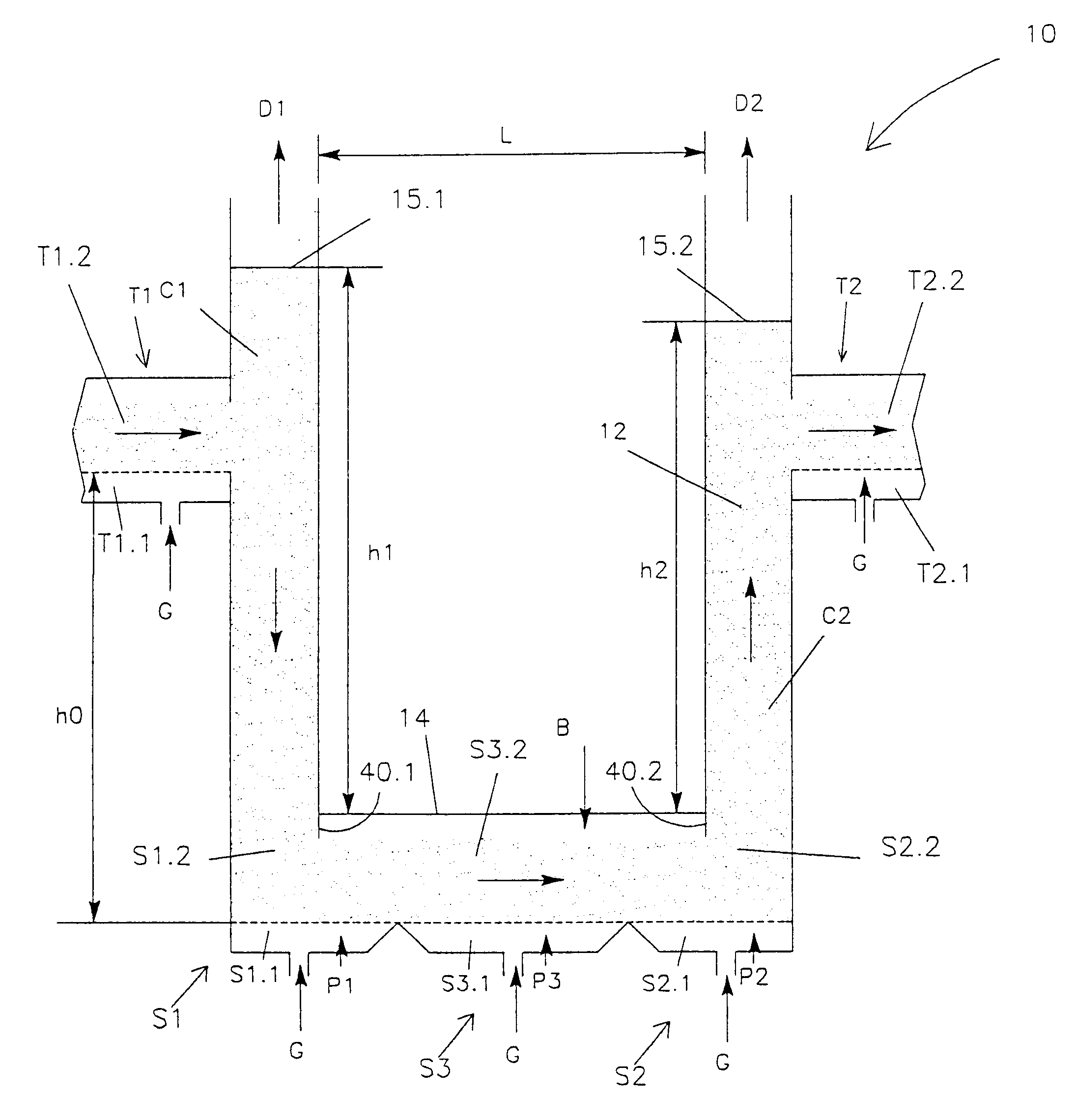
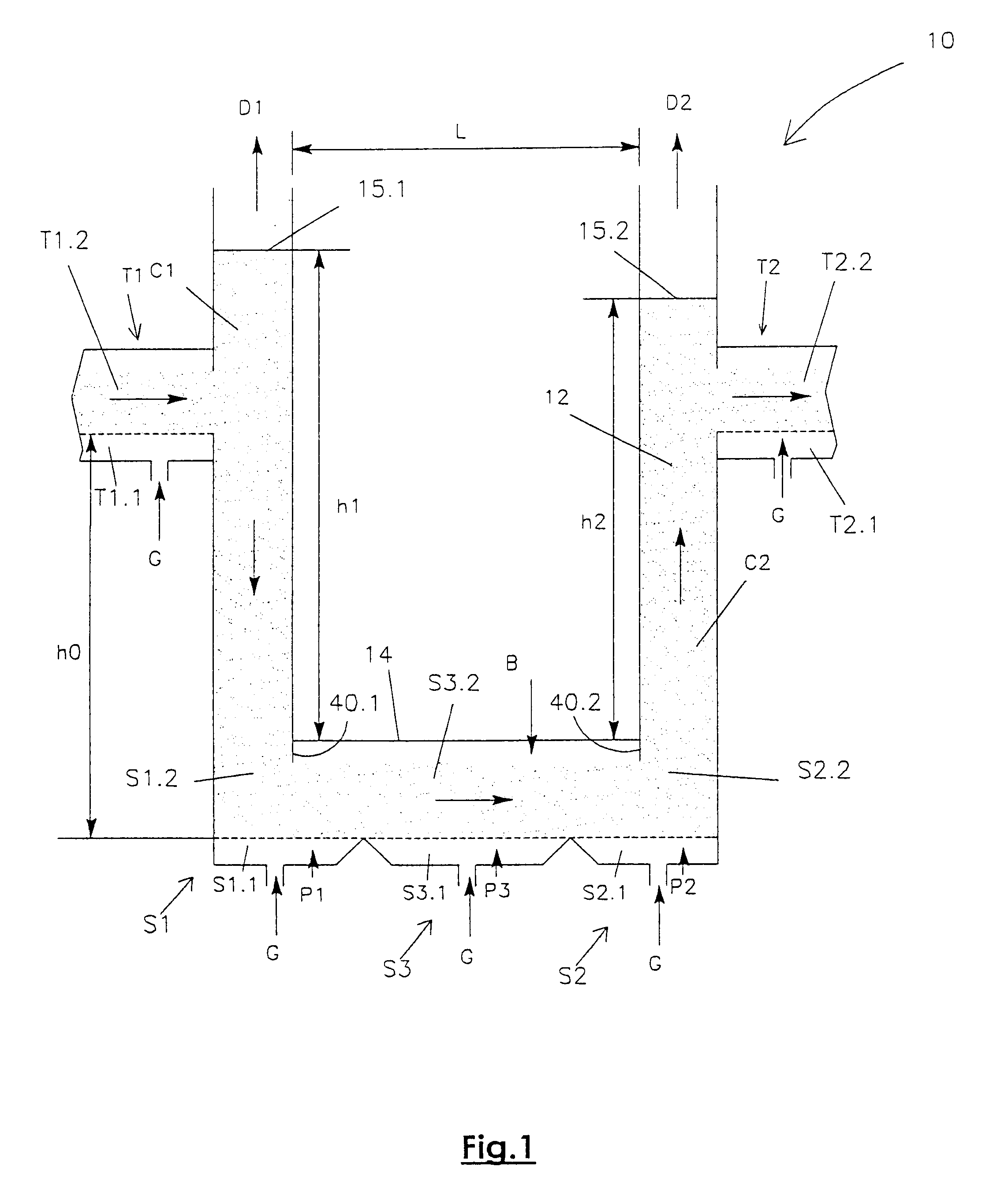
FIG. 3 illustrates a device used to bypass an obstacle by going over it. The various parts of the device are marked with the same references as those used in the example in FIG. 1 and in FIG. 2.

This type of device cannot operate in isolation. It is connected to the overhead storage tank by means of a set of air pipes represented in FIG. 3 by the air pipe T. As in the example 2, the upper level of alumina in this overhead storage tank 1 is often higher than the free levels of alumina in the columns of the bypass device, and particularly the upstream column (the height H of alumina must then be greater than the height h in column C1).

Advantages of the Process According th the Invevtion

This process is used to design and make hyperdense siphons used:

to supply electrolysis vats between two horizontal conveyors, passing under or over a free passage;

or for extraction from a silo when the silo is located close to the ground.


PUM


Abstract

Process for conveyance of a powder material in a hyperdense bed to bypass an obstacle, in which an obstacle bypass device including at least upstream, intermediate and downstream caissons is inserted between two horizontal conveyors, an upstream conveyor, and the downstream conveyor. At a device entry, at the upstream caisson lower duct is supplied with gas at pressure P1, the upstream caisson further including an upper duct which is a column. The intermediate caisson is between the upstream caisson and the downstream caisson at a level that bypasses the obstacle, a lower duct of which is fed with gas at pressure P3 and an upper duct of which is connected to the upper duct of the upstream caisson and to an upper duct of the downstream caisson. At a device outlet, at the downstream caisson, a lower duct is supplied with gas at pressure P2. The three caissons remain full of powder material kept in a potential fluidization state at all times, with a pressure difference P1-P2 being kept strictly positive.

Description

The invention relates to an improvement to the powder material conveyance and distribution system in hyperdense phase. This improvement makes it possible to equip existing industrial installations with this high performance and economic conveyance system.It is a continuous process for conveyance of a powder product in order to feed a large number of packaging assemblies such as bagging machines, containerization devices, or a large number of production assemblies such as plastic extruding presses or igneous electrolysis vat cells, from a single storage area.Powder materials to be conveyed can be fluidized; their size grading and cohesion are such that injecting gas into them at low velocity can eliminate cohesion between particles and reduce internal friction forces. For example, this type of material includes alumina for igneous electrolysis, cements, plasters, quick lime or slaked lime, fly ash, calcium fluoride, magnesium chloride, all types of fillers for mixes, catalysts, coal ...

Claims


Application Information

Patent Timeline
IPC IPC(8): B65G53/20B65G53/16B65G53/34B65G53/52B65G53/04
CPCB65G53/16B65G53/52B65G53/20
Inventor GASQUET, GERARDCLOUE, CHRISTIANTORSIELLO, STEPHANE
Owner ALUMINUM PECHINEY
Why Eureka
Try Eureka